HSS Connections: Sample Designs and Real-Life Application
In the world of structural engineering, precision and reliability are paramount. As professionals in the United Kingdom continue to push the boundaries of design, the demand for robust connections within steel structures is ever-present. That’s where HSS Connections come into play with its joint geometry, offering a blend of strength, efficiency, and versatility revolutionizing the field. A great example is Bird Beak Joints, where HSS connection plays a vital part.
Furthermore, we embark on a journey deep into the heart of HSS to HSS Connections, exploring sample designs and their basic principles. To get a demonstration of the HSS connections which provides a basic understanding of these connections, we used the example from Heathrow Airport.
Joint Geometry for HSS Connections
The main types of joints are covered in the picture below:
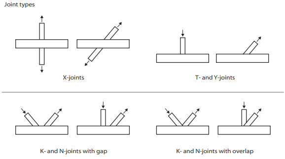
In terms of Joint Geometry, the angle formed by the chord and bracing or between two bracings must fall within the range of 30° to 90°.
In case the joint geometry angle is less than 30, then:
In Figure 2, below, K-and N-joints have overlapping bracings, then the overlap must be made with:
– Partial overlap where the first bracing runs through to the chord, and the second bracing sits on both the chord and the first bracing.
– Siting fully on the first bracing.
The designer must guarantee that a sufficiently strong weld can be created at the acute angle.
The joint resistance calculation should be made by applying an angle of 30 degrees, rather than a acute angle.
Figure 2:
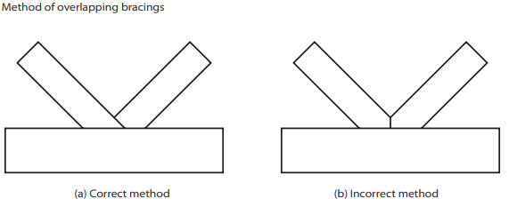
Figure 3:
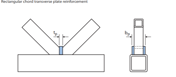
The creation of the joint by cutting the toes from each bracing and joining them together should never be done (figure 2b). This method is more challenging to assemble and can lead to decreased joint resistance. However, a modified version of the type of joint (figure 2a) can be used, provided that a plate of sufficient thickness is instead between the two bracings, as shown in Figure 3.
Validity ranges:
These ranges aid in ensuring that the modes of failure of the joints fall within the calculated limits of the design formulae. If the joints fall outside the limits of the design formulae, other failure modes, not mentioned in the formulae may become an issue.
For example, in Figure 1, if there is no check is required for chord shear in the gap between the bracings of circular K- and N-joints, this failure mode could become an issue outside the validity limit. However, If one of the geometric parameters falls outside the limits of the joint, then we would that the actual joint resistance could be reduced to about 0.85 times the calculated resistance using the design formulae.
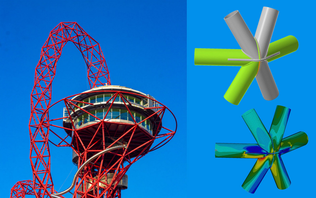
Multi-planar Hollow Section:
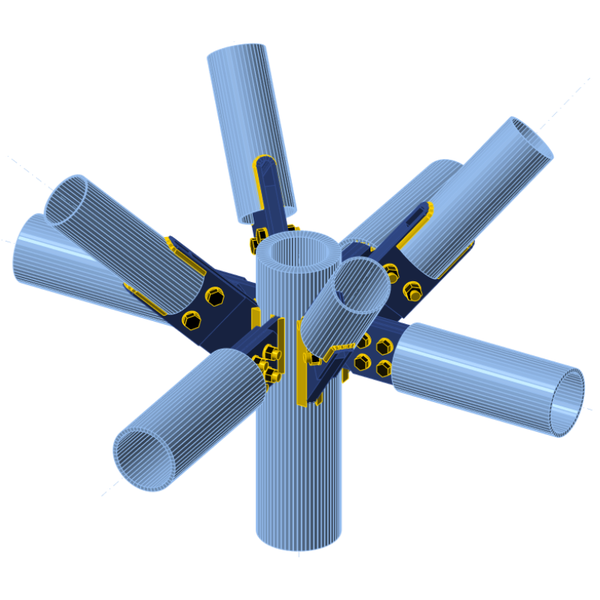
A complicated joint between various hollow sections. The horizontal beams and diagonal supports are secured to plates that have been welded to the main cylindrical column. Complex truss connections are primarily employed in tall buildings. The IDEA StatiCa Connection app was used to analyze the model.
Bird Beak Joints
Bird Beak Joints are complicated between various hollow sections. The horizontal beams and diagonal supports are secured to plates that have been welded to the main cylindrical column. Complex truss connections are primarily employed in tall buildings. The IDEA StatiCa Connection app was used to analyze the model such as this Bird Beak Joints
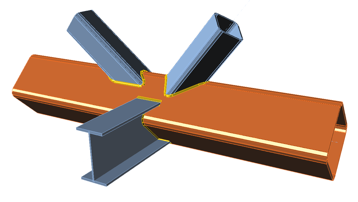
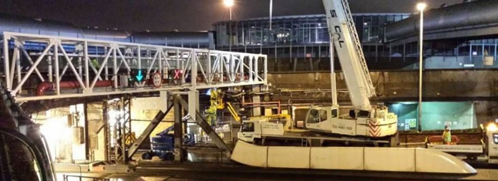
HSS connection real-life example: Heathrow Airport
In the project at Heathrow Airport, IDEA Connection was utilized for analyzing and designing connections in a steel truss structure composed of hollow sections.
Mott MacDonald, the original consulting engineer, designed the primary structure for the Heathrow Airport. The construction contractor, DHD Engineering, delegated Ellis & Moore Consulting Engineers with the task of designing the connections for the Heathrow Airport. The article can be accessed here: Ellis And Moore – Heathrow Airport – IDEA StatiCa.
This article, authored by Alexander Bezas, a structural engineer at Ellis & Moore, delves into the intricate aspects of connection design for this project. It highlights how IDEA Connection was instrumental in overcoming the challenges and discusses the use of the original component method specified in the Eurocode utilised in the Heathrow Airport project.