We develop software for structural engineers and detailers. Our development team researches, tests, and applies new methods of analyzing the behaviour of structures and their members. Based on this, we created IDEA StatiCa – software that enables engineers to work faster, evaluate requirements of the national code thoroughly, and use the optimal amount of material. For us, creating software is a way to contribute to making every new construction around the world safer and cheaper.
Beam to Column Connection Design: IDEA StatiCa In-depth Guide
This is a tutorial that utilises IDEA StatiCa Connection to promptly design and code-check steel connections. Through this article, we will illustrate how to model a simple steel connection, and also how to get code-check results and a detailed report, within minutes for Beam to Column connection design.
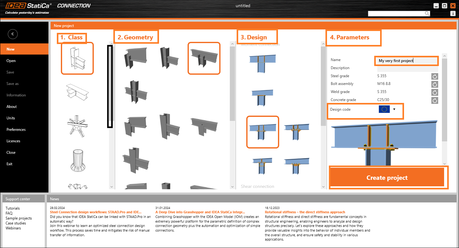
In the first step, you will be able to find a desirable simple connection in the template, based onClass, Geometry and Design.
In the parameterssection, you can name your project and define the default material (use S 355 steel) and your design code. You will also be able to change the choice of your material, or even add a new one later. However, the design code can only chosen during this initial stage of your project. Click onEurocode (EN).
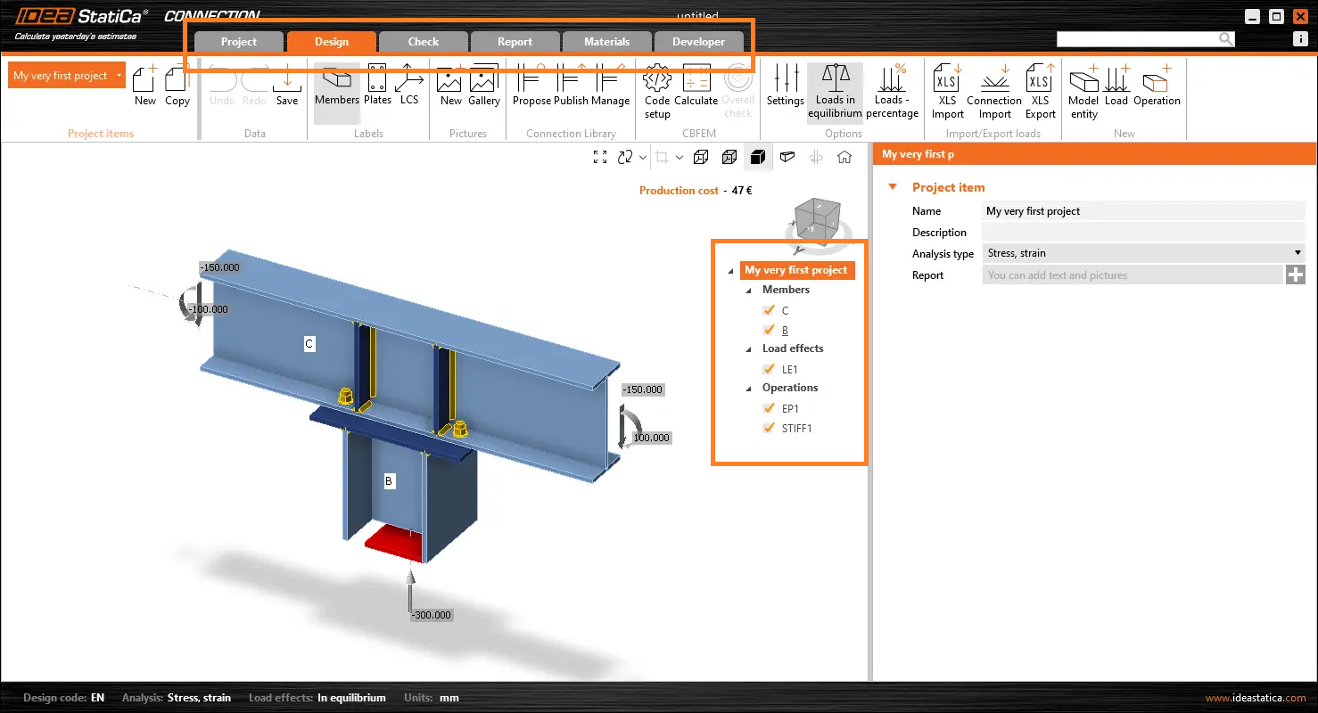
A new project will be created, based on the selected Class, Geometry, Design and Parameters template. In the top ribbon section, you will able to see various tabs that will give you a direction to work through your project. You are also able to make changes to the model view in the grey strip above the 3D scene.
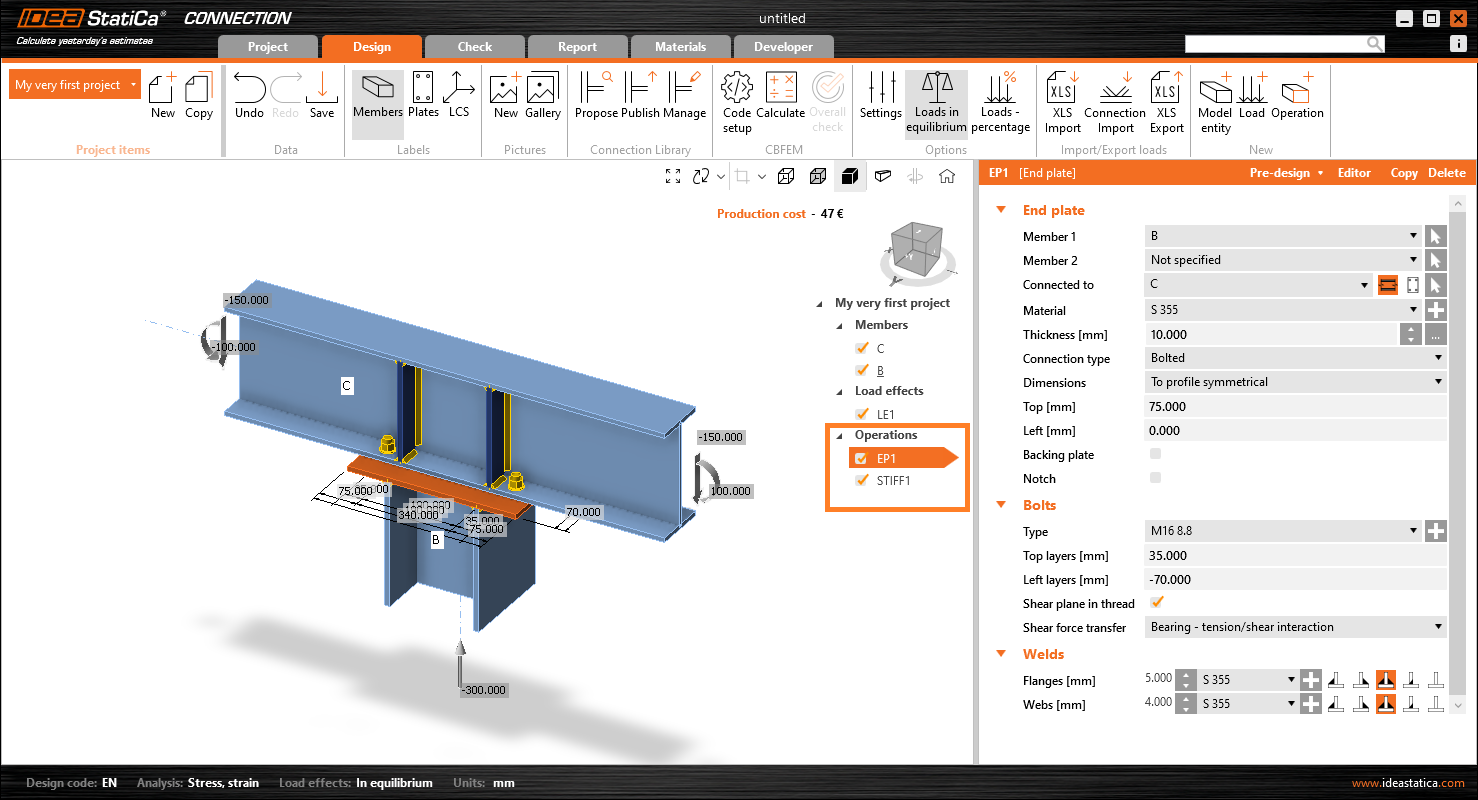
We will start in the Design tab, we will follow the sets of settings presented regarding Members, Load effects and Operations. This is known as the Tree section.
In theMemberssection, you can make adjustments to the parameters of your connection structural members, for example: orientation, cross-section, material, geometrical type and other structural elements.
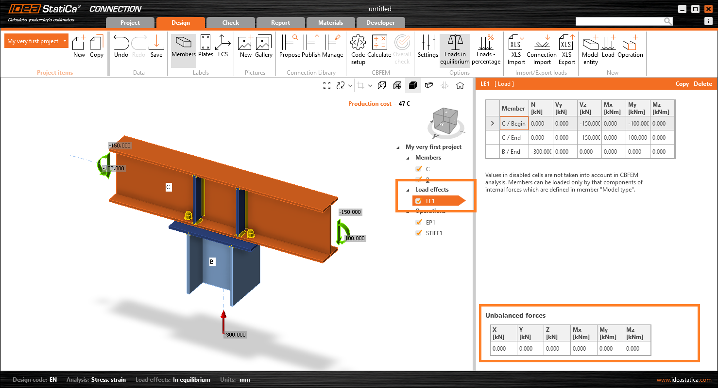
The second section of the Tree panel defines the load. It is crucial to define loads in equilibrium. More on this topic can be found here.
In the third section of the tree panel, the manufacturing operations are defined. In the selected connection, there are two options presented: an EP1operation of the endplate and a STIFF1 operation defining the stiffness on beam C. This allows you to change any parameter of the selected operations, or even delete or add another one.
2. Getting the results for Beam to Column Connection:
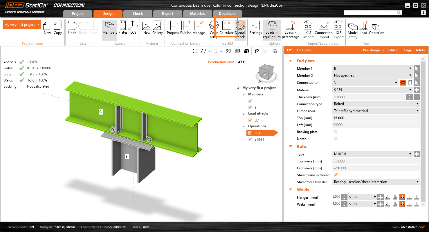
To initiate the calculation for the beam to column connection, click on the Calculatebutton on the top ribbon.
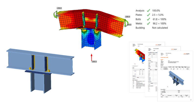
You will immediately be given the overall results, illustrating the utilisation level of each component for the beam to column connection. The colour grey indicates utilisation under 60-95%, orange indicates 90-100%, and finally red for utilisation over 100%. The read also indicates failing components.
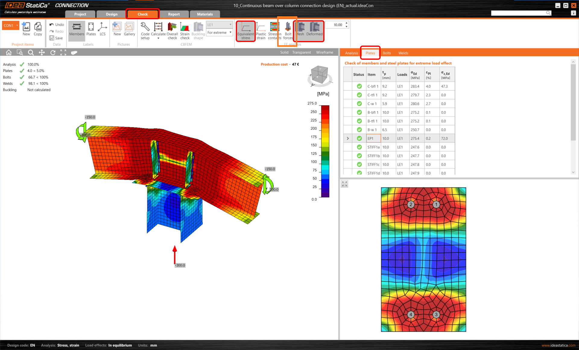
To see the detail results, you must click on theChecktab in the top ribbon.
This is the stage where you would be able to evaluate the results of each component of the connection. For example, in this case, let’s start with plates and investigate the Equivalent stress model, consisting of both Meshand Deformed.
In this case, we would click on the endplate shown, and the line that corresponds. The table gets highlighted while the plate is also displayed in the detailed window under the table.
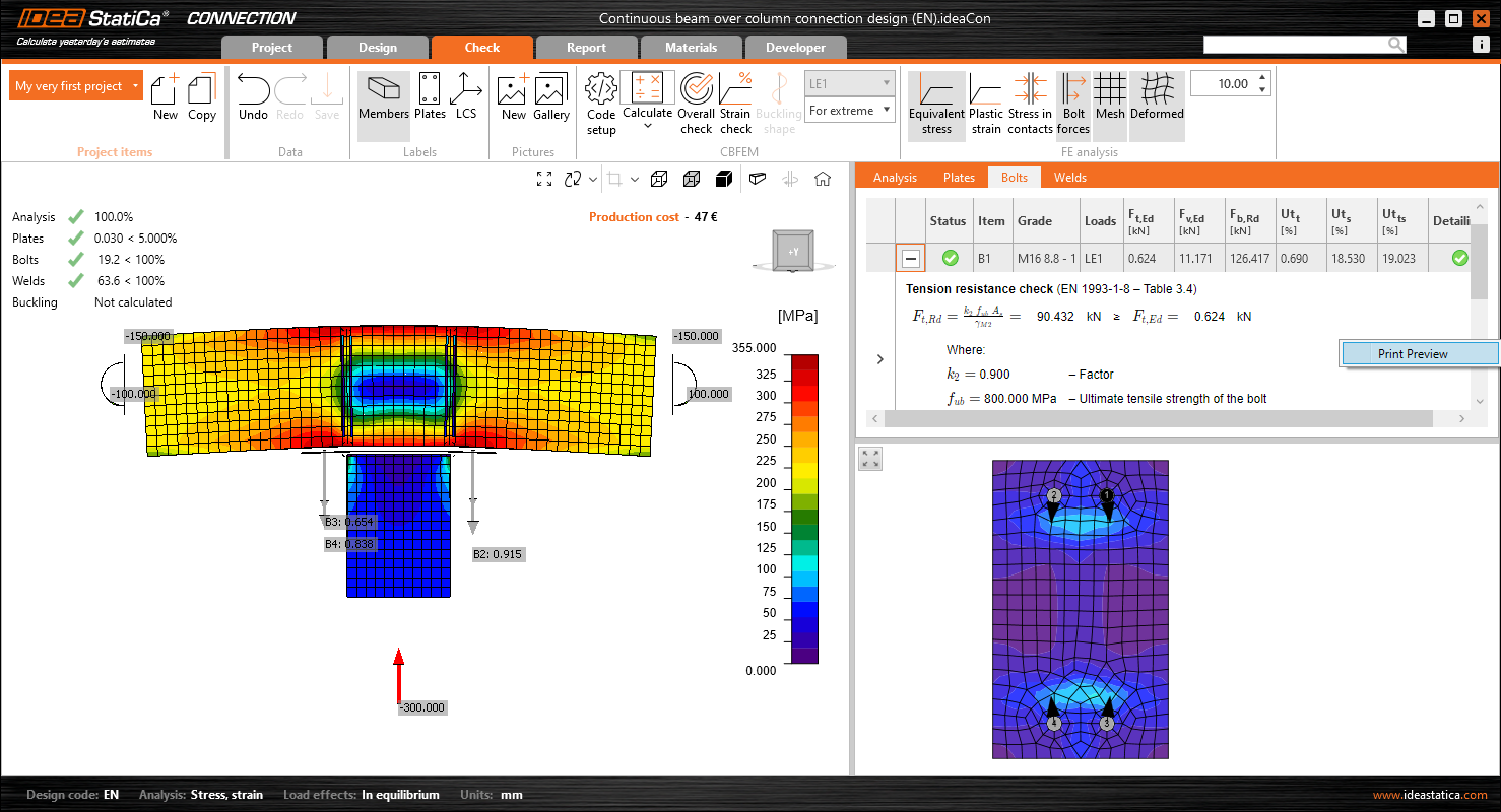
The next aspect of the results that can be gathered is the Bolts. To view the results, you must, first, change the table tab to Bolts, and turn on the Bolt forces in the top ribbon. This, as a result, would display the tensile forces in the 3D scene. Moreover, you can also select one of the bolts directly in the model display to see the corresponding results within the table. It will also show the real direction of the shear force, which is displayed at the bottom figure.
Additionally, to view all the equations required by the standard, click on the ‘+ button’ in the table line that it corresponds to. To see the larger view of this equation, right-click on the mouse toPrint Previewfor the beam to connection design.
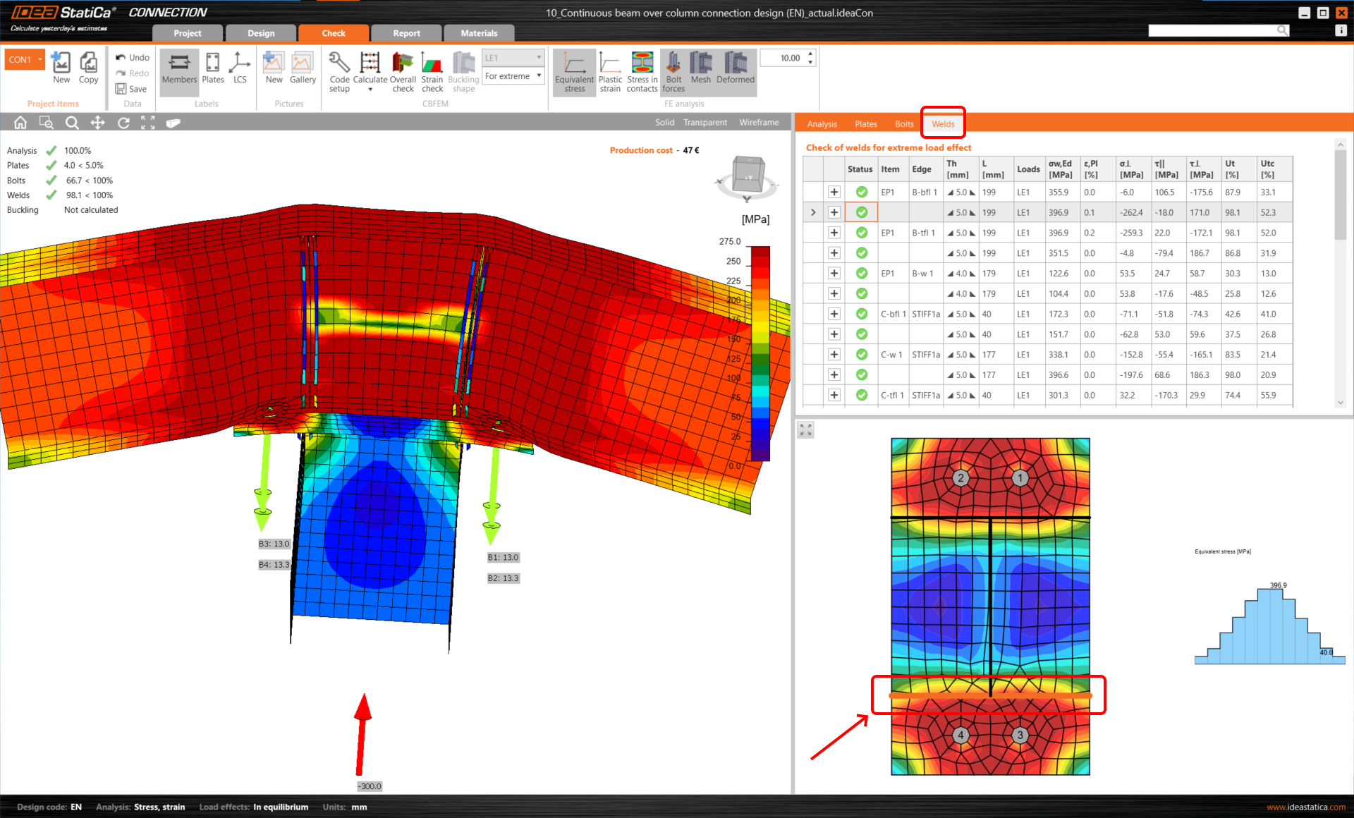
Similarly, the same can be done for welds. Again, clicking on the selected weld in the display model will illustrate the corresponding results, and also the stress distribution along the corresponding weld in the bottom figure.
3. Printing report
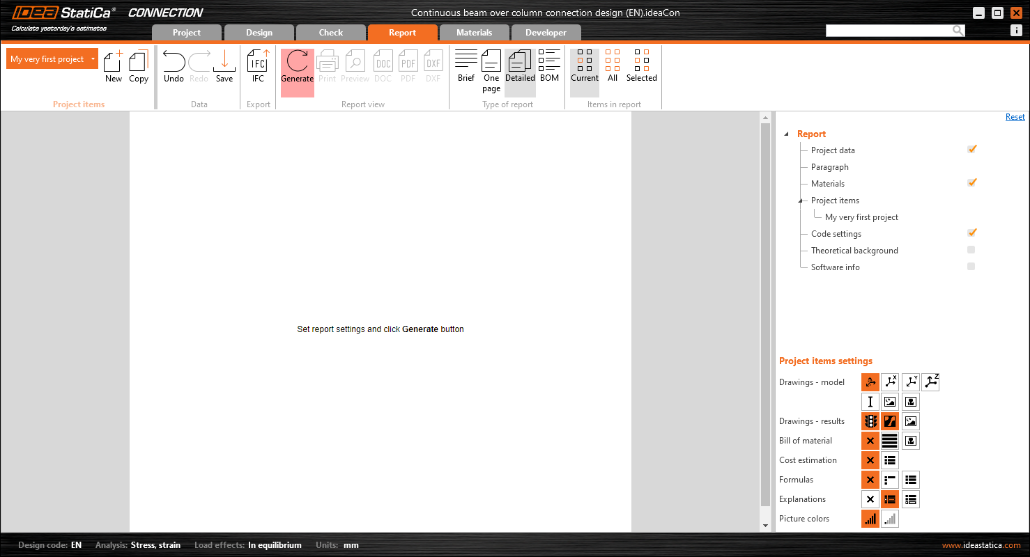
The next step is to print a report of your calculation, you can do so via the Report tab.
On the right side of the dashboard, you can make adjustments to the report based on your or your stakeholders’ needs. For example, we can also include the Bill of material within the report. Afterwards, by clicking on the report, then press Refreshfrom the top ribbon.
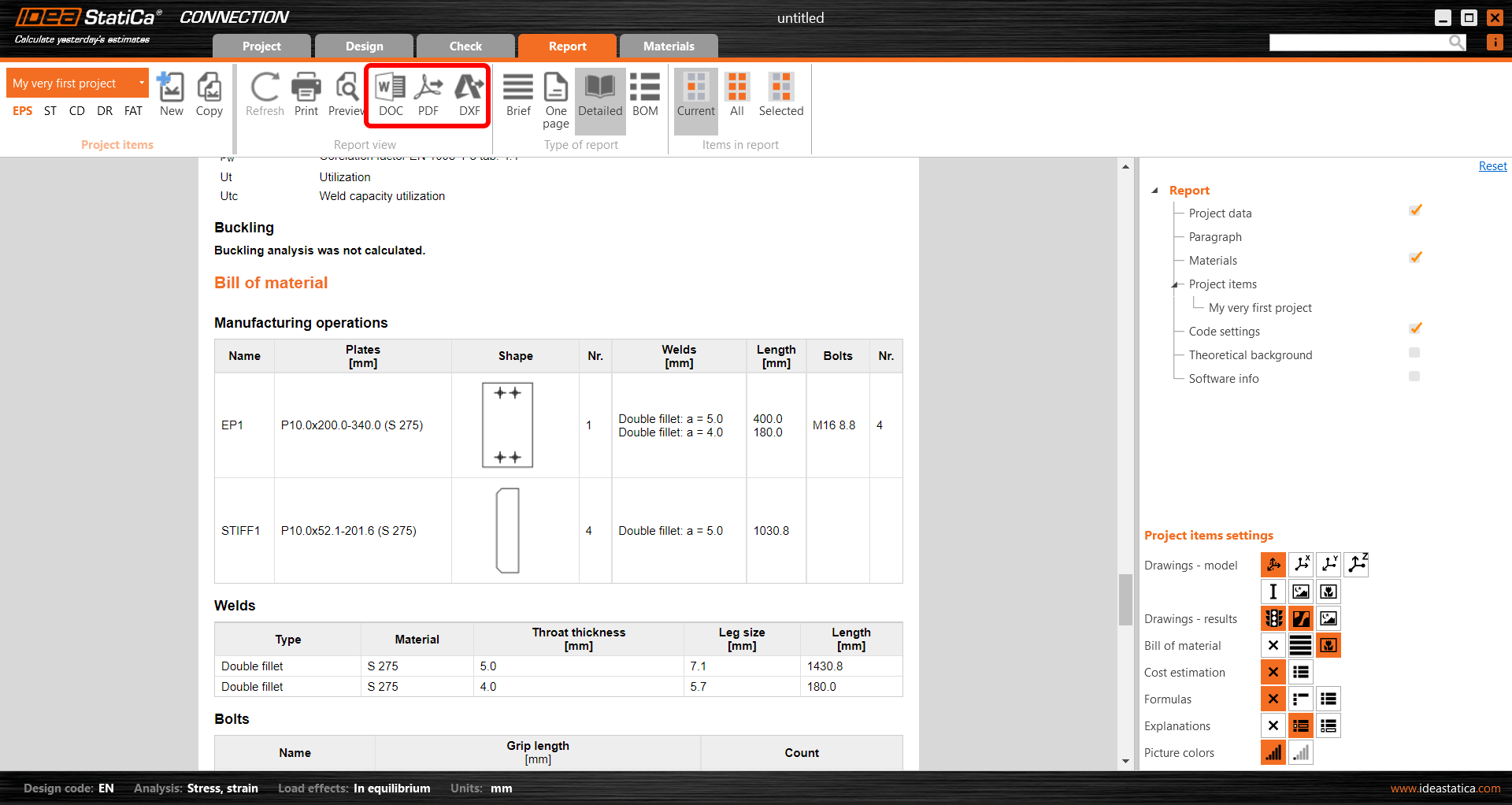
A bill of material will be generated and will be embedded in the report. This can be printed out in PDF and Microsoft Word format. Furthermore, you are also able to obtain the 2D drawings of your plates, this can be done by pressing the DXFbutton. To obtain the 3D model of your connection, you can download it, via our online Project Viewer.
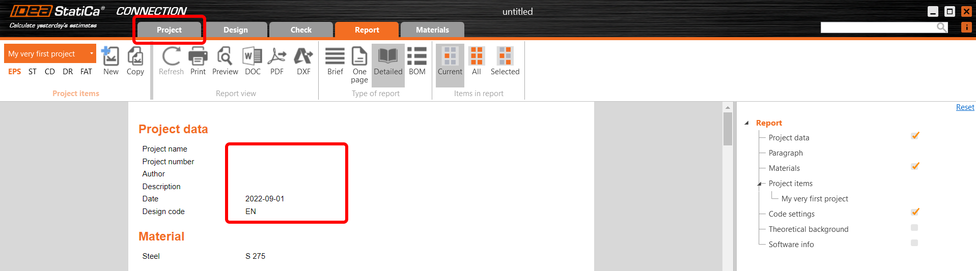
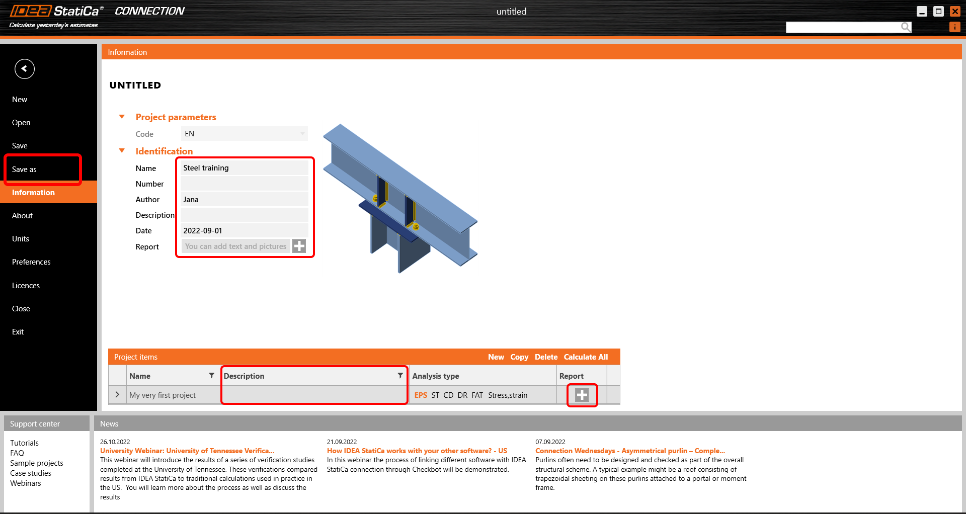
To change the headers of the report, you can go to the Project tab.
In this part, you can amend the name, author, date and description either to the whole project, or the individual project contribution.
Another crucial aspect is to Save your project and we are done!