We develop software for structural engineers and detailers. Our development team researches, tests, and applies new methods of analyzing the behaviour of structures and their members. Based on this, we created IDEA StatiCa – software that enables engineers to work faster, evaluate requirements of the national code thoroughly, and use the optimal amount of material. For us, creating software is a way to contribute to making every new construction around the world safer and cheaper.
Steel Pins Design with IDEA StatiCa
Pins are commonly used in various steel structures, typically for linking bracing, diagonal, rod and bar elements, or otaher structural elements that transfer tension and compression forces. This type of connector is now available in the IDEA StatiCa Connection application.
Pins can used when creating pin connections or in situations where a single bolt connection fails to satisfy the criteria present in EN 1993-1-8, 3.13.1 (2) and needs to be seen as a beam element subject to bending.
How to model a pin
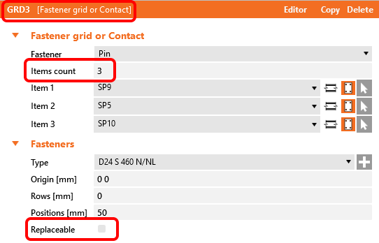
Pins can be found under the Fastener Grid and Contact operation. When a pin fastener is used, the number of items automatically adjusts to three, the minimum number of plates that can be connected.
The pin can be configured to be Replaceable, which dictates the checks used by the code.
A Member connected via a pin should be constrained at its loaded end using the N-Vy-Vz model type, otherwise, the evaluation results in a singularity due to rotation about the pin axis.
As with regular bolt operations, contact between plates is created automatically if the distance between connected parallel plates is less than 2mm.
Pins in the project material database
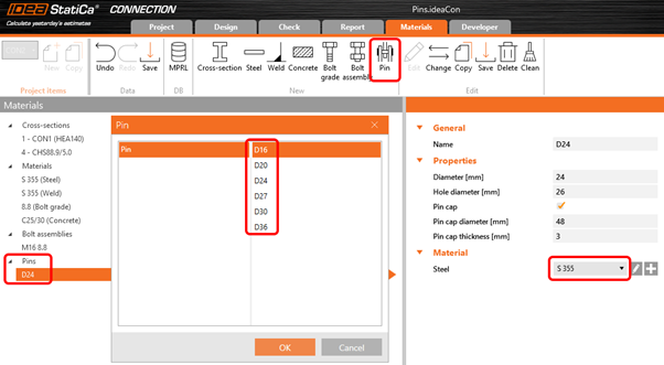
The geometric parameters of the pin (pin diameter, material, hole size, etc) can be defined in the Materials tab similarly to bolt assemblies. Thediameter of a pin can be selected from the predefined material library.
Structural steel material (e.g. S 355) is utilised as the default material for pins. In case a steel bolt material (e.g. 8.8) or any other type of material needs to be defined for pins then this can be done by editing the properties of the associated material via the Materials tab (fu, etc.).
APin capcan be activated; however, it doesn’t affect the inspections or evaluations, only the visual display of pins in the 3D environment.
Code checks of pinned connections
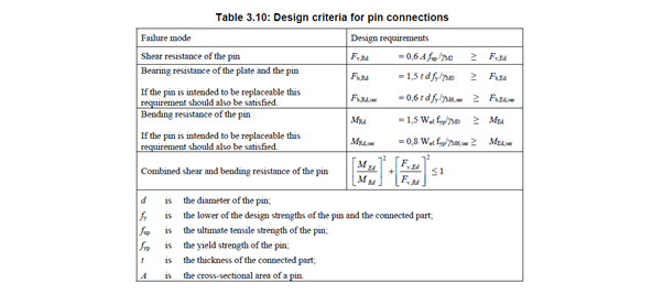
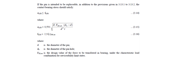
Checks are provided based on EN 1993-1-8, 3.13.2.
When the pin is labelled as replaceable, the checks conducted will then be based on Table 3.10 and Equation 3.14.
When analysing the model for itsfire resistance, thereplaceable property used with any pins in the model is ignored, and all pins in the model are considered as non-replaceable instead.
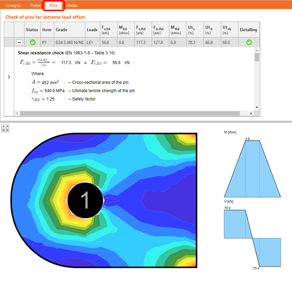
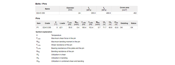
Pins in results and report
Atab for pin checksis available, featuring details of the conducted checks, and the associated equations used, in theCheck tab. Additionally, thediagram of the bending moment in the pin is shown, together with the stress/strain in the connected plate.
Thereport includes all input data and results related to pins used in the model.
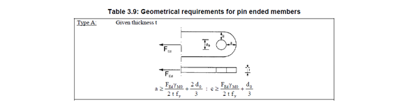
Detailing checks for pinned connections
Basic detailing checks are conducted as perTable 3.9 – category A. The same approach as the one used to calculate bolts’ edge distances(based on vector direction) is used to identify the pinedge distances“a” and “c”.
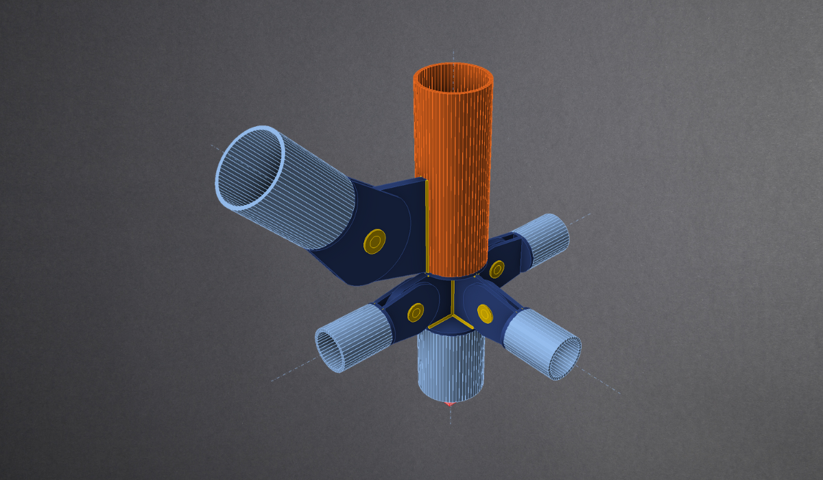
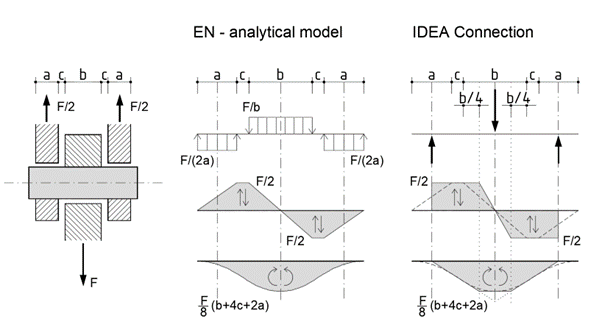
CBFEM analytical model of a pin
The Component-Based Finite Element Method (CBFEM) models pins as linear elastic beam elements. The pin model is designed to prevent any individual plates from connecting along the pin`s axis, ensuring that no normal force is resistedwithin a given pin. Only shear force and bending moment will develop in the fastener.
In the Connection application, forces are applied on a pin as point loads along the axis of the connected plates. The bending moment diagram within the pin has asimplified linear shape when contrasted with the analytical model in the Eurocode. Internal forces within the pin are calculated and displayed at a quarter of the inner plate’s thickness. This guarantees that the shear force and bending moment’s peak values utilised for code checks match the extreme values from the analytical Eurocode model.