We develop software for structural engineers and detailers. Our development team researches, tests, and applies new methods of analyzing the behaviour of structures and their members. Based on this, we created IDEA StatiCa – software that enables engineers to work faster, evaluate requirements of the national code thoroughly, and use the optimal amount of material. For us, creating software is a way to contribute to making every new construction around the world safer and cheaper.
Truss joint design with open sections
By:
Costis Hatzopoulos – Technical Manager at IDEA StatiCa UK
I really enjoyed reading David Brown’s article (Associate Director at the SCI), about the design of truss joints, composed solely from open sections, published in the January 2020 issue of New Steel Construction magazine (http://www.newsteelconstruction.com/wp/truss-joint-design-open-sections). The article presents the key points for calculating such configurations using the stock component method in the form contained in the Eurocode texts (if you haven’t read yet, I strongly advise you to do so).
The unconventional nature of these joints is revealed already in the header of the opening paragraph: “Conventional – or common?”. My interpretation of this sentence is that while this topology is widely used, the pitfalls involved in the correct application of the code provisions for its calculation are often overlooked.
Hand calculations require an element of creativity and experience, completely justifying the well-known fact that engineering is the crossing of science and art. In every form of art though, there are people who excel at what they do and then there are the rest of us who can just stand and admire their masterpieces. Unlike art, engineers need to apply such calculations daily under the pressure of strict deadlines.
As we are always keen on verifying IDEA StatiCa against established methods, David’s example was a perfect opportunity for us, since it addresses a common problem in a very detailed, comprehensive and accurate way. Using the same geometry, cross sections and loading, I recreated this in IDEA StatiCa, curious to see how they compare…
Modeling in IDEA StatiCa
Modeling this joint in the software is trivial, taking a minute or less, without the need to make any assumptions. The model just needs to reflect the actual member geometry.
This is also true for loading. In IDEA StatiCa, the user just needs to apply the loads in the relevant members while the first page of the article is dedicated in a discussion about load distribution between the section webs and flanges.
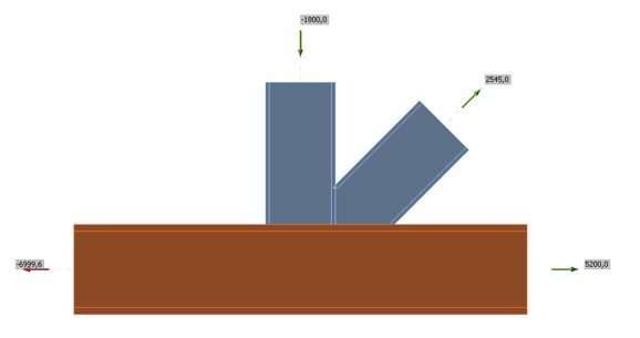
Figure 1- Connection topology
Another common issue that is easily addressed with the tools provided by IDEA StatiCa is that of `envelope` forces. Quoting David:
“Many connection designers will release anguished howls at this point, since in reality they are unfortunately often given ‘envelope’ forces which are not in equilibrium and therefore doubly challenging to address. For the purposes of this example, it is assumed that the force in the chord is 75% of its tension resistance”.
With our “Loads in equilibrium” we can easily create the condition of 75% of tension resistance in the chord while making sure that the connection is balanced (by zeroing out unbalanced forces).
No more howls in the office!
Calculation Results
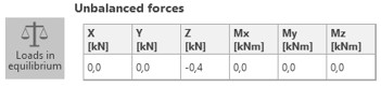
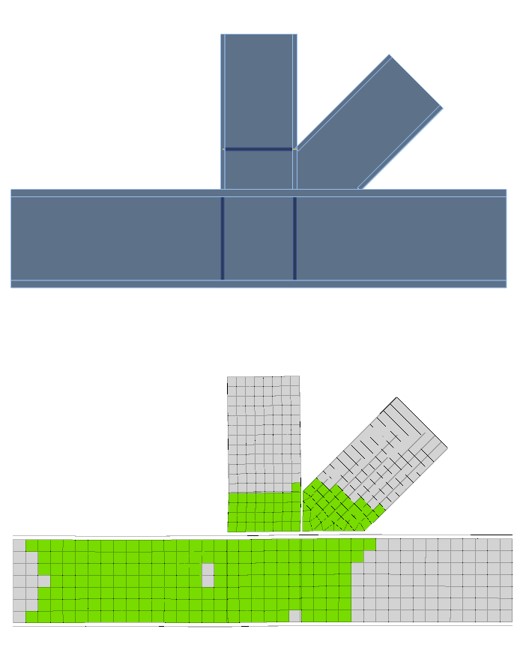
After loading the joint, the user simply needs to press the Calculate button and have a look at the strain check. This check visually reveals what David discusses extensively for almost one page. The red parts signify failure.
While identifying these parts in IDEA StatiCa is easy, it takes experience and tough decision making in the context of component method calculations. The critical points checked by David are displayed below and agree with his calculations.
Figure 3 - Original check positions overlay
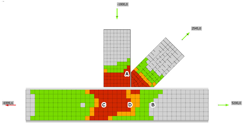
Moreover, the effects described by the component method can be revealed by activating the deformed shape tool which is a unique feature of IDEA StatiCa and an advantage of the applied CBFEM methodology. The user witnesses the deformation of the outer unstiffened flange tips.
To account for this fact, the code requires the assessment of an effective breadth were equal stress distribution can be assumed, provided that the calculation is performed from an experienced analyst who is familiar with these effects.
Especially for point B David explicitly mentions that:
“This is determined from Table 6.3, which leads backwards to Table 5.4 and a challenging decision on the value of β to be taken. After some consideration, the situation seems most like the shear in a web panel from a one sided moment connection, so β = 1. After a frustrating trip back to BS EN 1993-1-1 to calculate the shear area, ω is computed to be 0.82”
Again, all these effects are accounted for by the underlying CBFEM material model, so the user does not need to make any special considerations. Connection design does not need to be frustrating!
Figure 4 - Flexible tips of unstiffened flanges deforming
Reinforcing the Connection
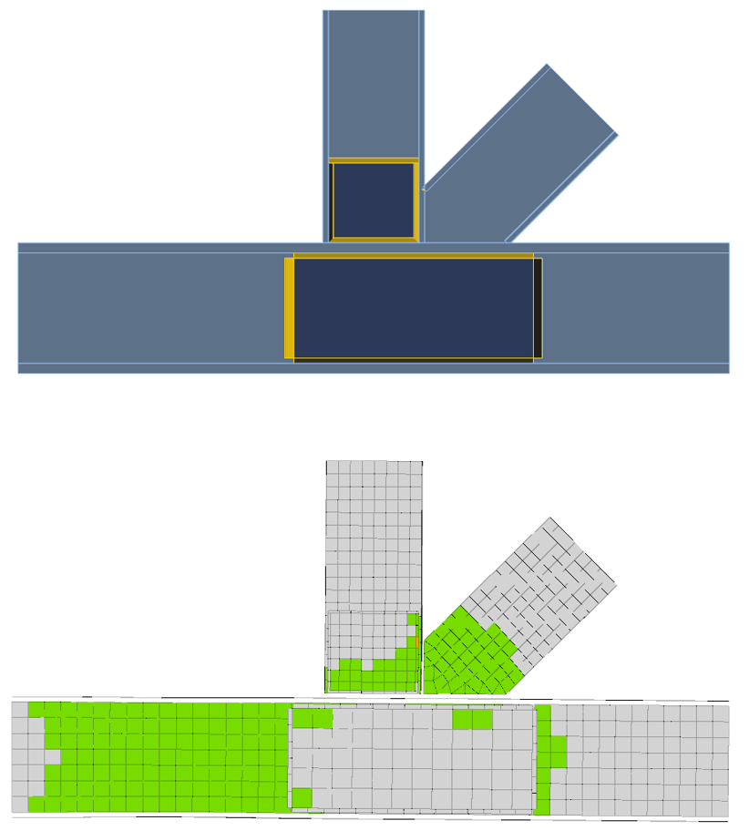
It is obvious that adding stiffeners after David’s proposal can heal this connection. Adding these in IDEA StatiCa and solving again is a matter of seconds. The results agree with the ones from the article and the connection passes all checks.
Figure 5 - Stiffened connection model and results
As an exercise David examines also the use of web doubler plates. The use of code provisions poses additional problems:
“Because of limited research, the contribution of a supplementary web plate is limited to a maximum thickness equal to the web it reinforces, even if the additional plate is thicker than the web. Adding a plate to the other side of the web makes no further increase in the shear resistance, which seems implausible.”
Again, this is not a problem for IDEA StatiCa as the model can be adapted and solved in seconds. Exploiting a feature of IDEA StatiCa, the doubler plates inherit the thickness of the relevant web, in order to have results directly comparable to that of the component method calculation.
Figure 6 - Model stiffened with doubler plates
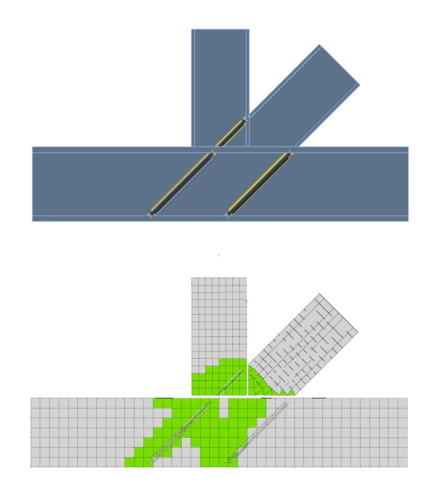
Last, David mentions that a variation with diagonal stiffeners could be developed, although there is rather limited room for those.
One can understand that hand calculations of this alternative geometry would take a lot of time and probably would be skipped due to project time constraints. This is a non-issue for IDEA StatiCa, since various alternatives can be modelled and analyzed very quickly. So, let’s try this one also! It’ only a matter of seconds anyway…
Figure 7 - Model stiffened with diagonal stiffeners
Conclusion
I was happy to find out that my IDEA StatiCa calculations have very good agreement with David Brown’s ones in the aforementioned article.
The only difference being that the user of IDEA StatiCa does not need to disrupt his normal workflow or make any tough decisions to model and design these configurations. They can be modelled in minutes and produce the expected results.
Moreover, the user can experiment easily with different reinforcement configurations to decide which the optimal solution is for each given use-case.