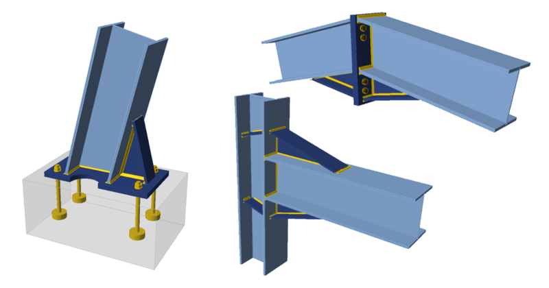
There are many types of moment connections all around us, but what do we need them for? How to design them effectively and in accordance with national codes? Take a look at our grand connection overview.
Generally speaking, the Moment Connection is a joint that besides normal and shear forces, allows the transfer of bending moment forces between two structural members or from the structure to the foundation.
Some type of moment connection can be found in almost every structure, but their typical use is in:
- transverse frames of steel halls
- frames of multi-storey structures
- stiffening frames alternatives for bracing fields
There are several types of their classification:
Acc. to the cross-section used:
- Open sections
- Hollow sections
- Combined
Acc. to the connection elements:
- Welded (only)
- Bolted (only)
- Combined
Acc. to the use in the seismic structures:
- Seismic
- Non-seismic
Acc. to the typology
- Full-depth end plate
- Extended end plate
- Stiffened extended end plate
- Haunched beam
- etc.
Most often, when we speak about the moment connections, we mention rigid connections. But we shouldn’t forget about Semi-Rigid (or Partially restrained) connections, which can also transfer significant bending moments. Stiffness of the moment connection is crucial and you can find useful information in our blog post focused on this topic.
From the structural design perspective, the world consists of two types of mainland regions: seismic active and seismic non-active.
It is the location of the designed structure that is crucial for the options and limits considering by the designer. When the structure needs to be treated as a seismic structure, the global structural model has to be adjusted very precisely to the expected behaviour under seismic loading. The structural lateral stiffness has to be secured with an appropriate structural typology. For this purpose, the structural engineers mainly reach for diagonal bracings, shear walls or moment-resisting frames (MRF).
AISC seismic connections
There is a list of appropriate connections for these frames, given by US design guidelines. They are known as Prequalified Connections specified in ANSI/AISC 358-16.
You can find some examples in the pictures below:
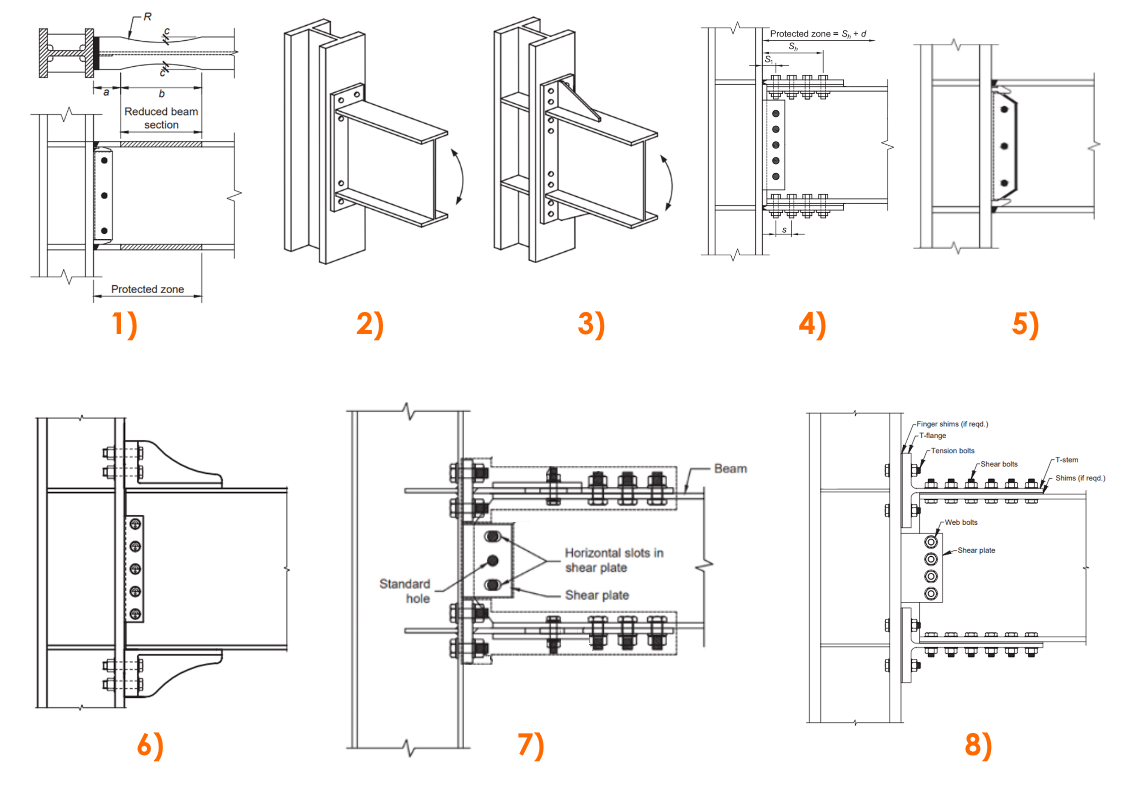
- Reduced beam section (RBS)
- Bolted unstiffened extended end plate (BUEEP)
- Bolted stiffened extended end plate (BSEEP)
- Bolted flange plate (BFP)
- Welded unreinforced flange – welded web (WUF-W)
- Kaiser bolted bracket (KBB)
- Simpson Strong-Tie (Strong Frame) moment connection
- Double-tee moment connection
Moment Connections for HSS (hollow steel sections)
As we mentioned earlier, the moment connections are not suitable for open sections only. Very often you want or need to use the hollow section as well. So do we have any options? Yes, we do:
- Continuous Beam Over HSS Column Connections
- Through-Plate Moment Connections
- Cut-out / Collared Plate Moment Connections
- Welded Tee Flange Moment Connections
- End Plate Moment Connections
- Diaphragm Plate Moment Connections
- Directly Welded Connections
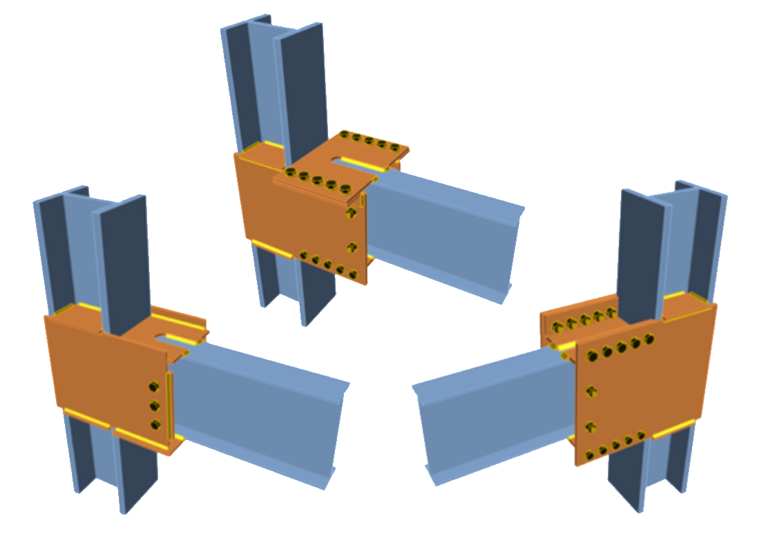
Some could say: Yeah, but the HSS are not allowed for pre-qualified seismic connections. That’s true unless you use them in SidePlate moment connection types.
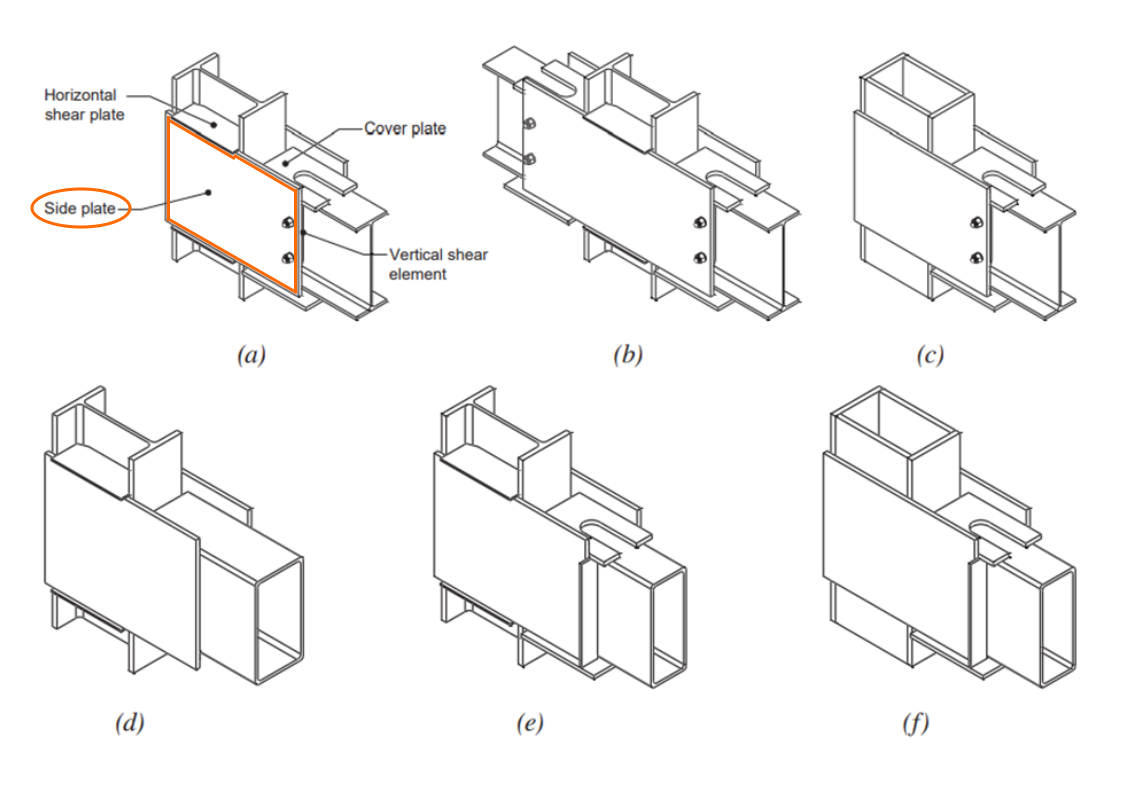
(a) one-sided wideflange beam and column construction;
(b) two-sided wide-flange beam and column construction;
(c) wide-flange beam to either HSS or built-up box column;
(d) HSS beam without cover plates to wide-flange column;
(e) HSS beam with cover plates to wide-flange column;
(f) HSS beam with cover plates to either HSS or built-up box column
IDEA StatiCa Connection has prepared templates even for these quite rarely used and complicated connection types. You can save a lot of time by using them.
EN seismic connections – Equaljoints
The continual efforts to adapt seismic connections also in European steel structural design codes are present for a considerable amount of time.
A project called Equaljoints is currently being developed by ECCS (European Convention for Constructional Steelwork) within the activities aimed at establishing guidelines for the design of seismic connections for the Eurocodes standardization.
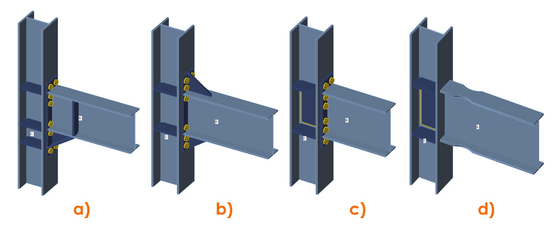
a) Haunched connection
b) Extended stiffened endplate joint
c) Extended unstiffened endplate joint
d) Dog-bone joints
This project will provide prequalification criteria of steel joints for the next version of EN 1998-1: Design of structures for earthquake resistance. IDEA StatiCa participates in this project and the experimental results were compared with the results from CBFEM analysis incorporated in the Connection app. You can take a look here at how the experiments and verifications are carried out in practice.
Stiffeners
When you need to transfer a huge bending moment from one member to another you often have to add some plate stiffeners to keep the continuity of the force flow. But where and how to design them properly?
Well, sometimes it’s the structure itself that limits the options and we have to adjust the design to other structural elements. On the other side, when you have the luxury to design the stiffeners according to the best of your knowledge, you should be aware of available options.
Some of the examples for stiffeners arrangement:

Cost optimization
The moment connections are not the cheapest ones. In fact, they can be the most expensive part of the whole structure when the production, transportation and erection are taken into account.
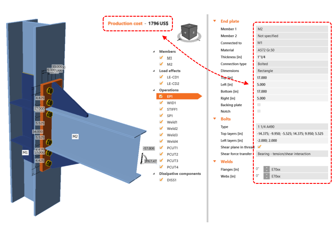
There is always a huge number of possibilities of how to design the particular connection but the experience helps us to choose the correct one. One great feature that can help you with the choice of the most appropriate and effective design is the Production cost calculator, which shows you immediately how the design changes influence the price.
Calculation and assessment
There are many ways and tools for the calculation and assessment of the specific moment connection type. You can find many applications which provide code-checks for particular connection arrangements. But if you want to assess literally any of them, the list of your options narrows. If your connection isn’t part of separated members only and is embedded in spatial structure with other members connected, you have only two options left:
1) The first one is to model the whole connection set as a shell non-linear model in some advanced FEA applications without the possibility of code-check according to a specific standard.
2) The second option is to use the IDEA StatiCa Connection application. In this case, you have no limitations in modeling and analyses. In a few minutes, you prepare the bolt, weld and stress-strain checks right according to the selected design code.
Just select your template, edit it, optimize according to the results and assess all checks needed in few minutes:

This article was written by:

Jan Kubicek
Product Engineer IDEA StatiCa

