Walls are essential elements in almost all structures. The other bearing parts of the structures as beams, plates, etc. are dependant on them. The underestimation of wall design can cause inadmissible deformation or even collapse of the whole structure. Let’s check it out, what approach for designing and code-check is hidden in the IDEA StatiCa.
Walls can be sorted according to material, purpose, or bearing function. If we focus on the material point of view walls can be built from steel, wood, or composite, but we will aim at concrete walls, their benefits, and design in practice.
Concrete walls are part of almost all structures like bridges, buildings, or liquid retaining and containment structures. For the preservation of the long-term service of the structure, it is important to cover crack widths, inadmissible deformations, stability points of view, or rheology effects of the concrete. The mentioned effects should be involved in the internal forces which will be assessed according to codes. Let’s check it out, how could this help us with the applications from the family IDEA StatiCa?
Walls in BIM
The evolution of the finite element method enables us to calculate any shape of the structure. The main question is then, how to interpret the results of the analysis and do correctly the code-check of shells/ walls.
For frequently used elements or part of the structures, the majority of engineers use their own excel spreadsheets coded by themselves. But, what will happen, if the new project comes and the excel spreadsheet seems insufficient?
At this moment, there are two options available. To have another tool for code-check or start seeking the new software, which does not have the drawbacks of an excel spreadsheet.
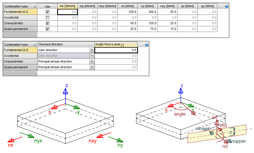
The global analysis has been performed and the internal forces on the wall can be inserted 1:1 to IDEA StatiCa RCS. Internal forces from the global analysis are automatically recalculated according to Baumann’s theory to the design internal forces where is considered the effect of shear stress flow in the wall for designing the reinforcement. The final steps are putting the reinforcement, selecting the code, and running the analysis.
The stability code-check ought to be performed in the global FEM analysis to prevent the buckling of the wall. This code-check is not on the menu of the code-checks in IDEA StatiCa RCS. More information about the method and analysis of the walls is in the theoretical background RCS for 2D members.
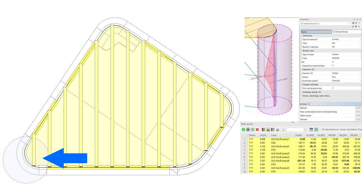
The same approach was used by one of our customers for a project in the United Kingdom, where the internal forces were integrated along with the height of the wall. Due to this, the process should be checked the wall as a 1D member in the RCS. The detailed workflow of the analysis and code – check is published in the case study Curved shear wall design, United Kingdom.
Walls in BIM
At this moment probably all of you would say: “Why we should bother with the copying of internal forces if we could use the elegant solution via BIM.”
BIM is one of the big topics for many years already and we in IDEA StatiCa follow the stream as well. Software like Midas Civil and AxisVM support the export of 2D shells/walls via BIM link to IDEA StatiCa. The workflow starts at the calculation of the internal forces in the global FEM program and subsequently comes the export via BIM link to IDEA StatiCa BIM, where part or all structure is exported.
The BIM interface serves for the selection of desired code, national annex, and the last step is code-check of ultimate limit state and serviceability limit state. The refresh and restoration of the results in IDEA due to change the loads in the FEM software are available and provide a quick optimization process. All the settings of the cuts, reinforcement, or code are preserved. The process saves time and money in the projects.

Walls in IDEA StatiCa Detail
How we handle walls which do not fit to the box standard like the walls with big openings or non-standard shape?
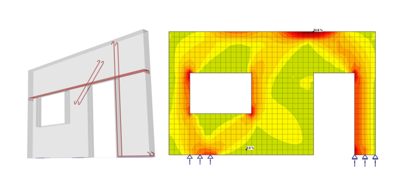
Indeed, we have the answer, and it is our IDEA StatiCa Detail. The new method CSFM (Compatible stress field method) used in this application introduces a unique solution of so-called D-regions also known as the discontinuity regions. The dapped ends, frame corners, walls with openings are fitting to the D-regions. The physically non-linear 2D solution of plane stress under the shield of CSFM brings to engineer the powerful tool for analysis and mainly code-check of the structure. The company www.betkoprojekt.sk used the CSFM in the area where other tools were insufficient.

The part of the project was analysis and code-check of the critical place where forces were transferred from the steel truss structure to the concrete wall. The problem occurred at the top-left part of the wall, where the code-check for concrete cone break out was not passed. The calculation was performed in the application IDEA StatiCa Connection, where is used cracked and unreinforced model of the concrete based on Winkler’s theory. The forces in the anchors were transferred to the wall in IDEA StatiCa Detail, where was applied the reinforcement and the forces were transferred by wire fabrics and additional reinforcement. Due to the complex model was the area of the anchoring and all model code – checked according to ULS and SLS. The advanced CSFM analysis confirmed the reliability of the anchoring and the whole structure.
The whole workflow was mapped and used in the webinar Cast in situ wall – Ruzomberok (Slovakia). The recording is available for free on the above-mentioned link.
