We develop software for structural engineers and detailers. Our development team researches, tests, and applies new methods of analyzing the behaviour of structures and their members. Based on this, we created IDEA StatiCa – software that enables engineers to work faster, evaluate requirements of the national code thoroughly, and use the optimal amount of material. For us, creating software is a way to contribute to making every new construction around the world safer and cheaper.
Bolts and bolted connections
Bolts and welds are the most difficult elements in the design of steel connections. Excel spreadsheets very often simplify their calculation. Modeling them in general FEM programs is complicated because these programs do not offer the predefined sets of elements. That is why the CBFEM method was developed and implemented into IDEA StatiCa.
Bolt model according to CBFEM
IDEA StatiCa has a unique method in its solver, the Component-based Finite Element Method (CBFEM). The bolt model used in CBFEM is described and verified in several steel design codes. The load resistance and deformation capacity are also compared to the main experimental research programs.
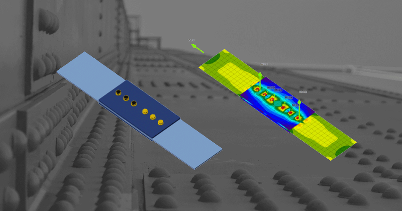
In the Component-Based Finite Element Method (CBFEM), a bolt with its behaviour in tension, shear, and bearing is the component described by the dependent nonlinear springs. The bolt in tension is described by the spring with its axial initial stiffness, design resistance, initialization of yielding, and deformation capacity. For the initialization of yielding and deformation capacity, it is assumed that plastic deformation occurs in the threaded part of the bolt shank only.
Let’s take a look at how CBFEM approaches bolts from the point of view of individual design codes. So far, IDEA StatiCa supports eight design codes where design and/or detailing of bolts and preloaded bolts are being solved.
Check of bolts and preloaded bolts according to Eurocode
The initial stiffness and design resistance of bolts in shear are in CBFEM modeled according to Cl. 3.6 and 6.3.2 in EN 1993-1-8. The spring representing bearing and tension has a bi-linear force-deformation behavior with an initial stiffness and design resistance according to Cl. 3.6 and 6.3.2 in EN 1993-1-8.
Detailing
Checks of bolts is performed if the option is selected in Code setup. Dimensions from bolt center to plate edges and between bolts are checked. Edge distance e = 1.2 and spacing between bolts p = 2.2 are recommended in Table 3.3 in EN 1993-1-8. Users can modify both values in the Code setup.
Check of bolts and preloaded bolts according to AISC
The forces in bolts are determined by finite element analysis. The tensile forces include prying forces. The bolt resistances are checked according to AISC 360 – Chapter J3.
Detailing
The minimum spacing between bolts and distance to the bolt center to an edge of a connected part is checked. The minimum spacing 2.66 times (editable in Code setup) the nominal bolt diameter between centers of bolts is checked according to AISC 360-16 – J.3.3. The minimum distance to the bolt center to an edge of a connected part is checked according to AISC 360-16 – J.3.4; the values are in Table J3.4 and J3.4M.
Check of bolts and preloaded bolts according to other standards
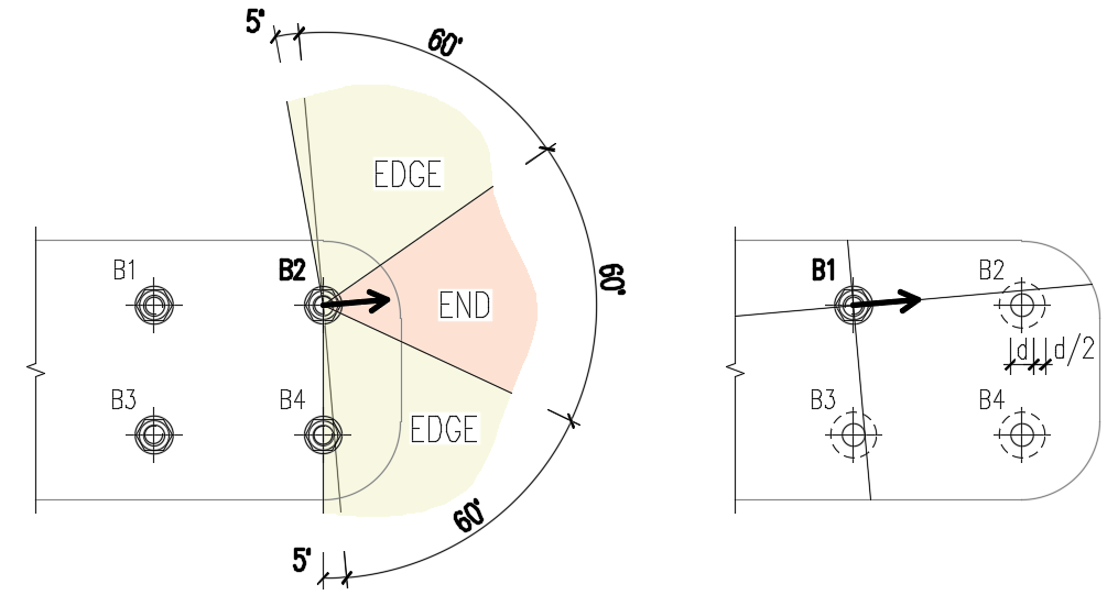
Edge distances used for bolt bearing resistance must be relevant for general plate geometries, plates with openings, cutouts, etc. The algorithm reads the real direction of the resulting shear force vector in a given bolt and then calculates the distances needed for the bearing check.
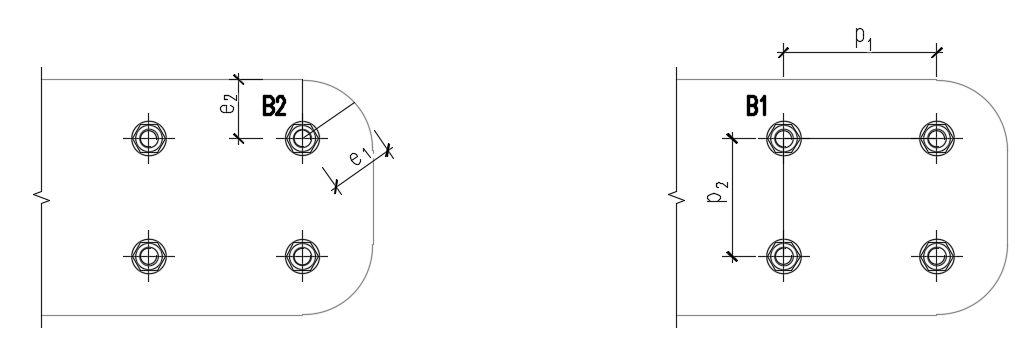
The end (e1) and edge (e2) distances are determined by dividing the plate contour into three segments. The end segment is indicated by a 60° range in the direction of the force vector. The edge segments are defined by two 65° ranges perpendicular to the force vector. The shortest distance from a bolt to a relevant segment is then taken as an end, or an edge distance.
The spacing distances between bolt holes (p1; p2) are determined by virtually enlarging the surrounding bolt holes by a half of their diameter, then drawing two lines in direction and perpendicular to the shear force vector. The distances to the enlarged bolt holes that are intersected by these lines are then considered as p1 and p2 in the calculation.
Verification examples
We have prepared several verification examples to check the results in comparison with other computation methods.
Do you know that our bolt model solution is a part of a U.S. patent? Read here about our success story.
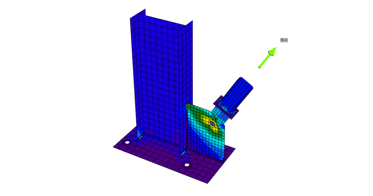
One bolt joint – our solution
Sometimes, the engineer needs to make a joint with one bolt only, especially if e.g. a hinge, a bracing, a rod, or a diagonal is expected. To model and calculate this kind of operation, you need to define a proper Model type of the member. More about it can be read here.
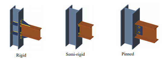
Bolts, welds, and stiffness of a joint
Both bolts and welds have their advantages and disadvantages. One of the important aspects when choosing a joint is its planned stiffness. In general, a bolted joint is never as rigid as a welded joint. If you choose a bolt connection, we recommend calculating the stiffness of such a connection and taking into account the resulting stiffness in the overall structure. You can read what such a calculation looks like and what it entails here, or watch this video.