We develop software for structural engineers and detailers. Our development team researches, tests, and applies new methods of analyzing the behaviour of structures and their members. Based on this, we created IDEA StatiCa – software that enables engineers to work faster, evaluate requirements of the national code thoroughly, and use the optimal amount of material. For us, creating software is a way to contribute to making every new construction around the world safer and cheaper.
Why bother with connection stiffness
In many projects, engineers don’t deal with connection stiffness, although it could be used as a great tool for design efficiency improvement.
During the analysis of every structural model, an Engineer has to define the type of each connection between members. As the model should represent the real behavior of the structure, an engineer has to predict what type of connection suits best.
A good approximation of the model to the real structure is important especially in the field of steel structures, where linear members are used most often. Steel structures are widely used for their effectiveness.
To obtain the best outputs, designers are often forced to optimize not only member cross-sections but also the design of connections.
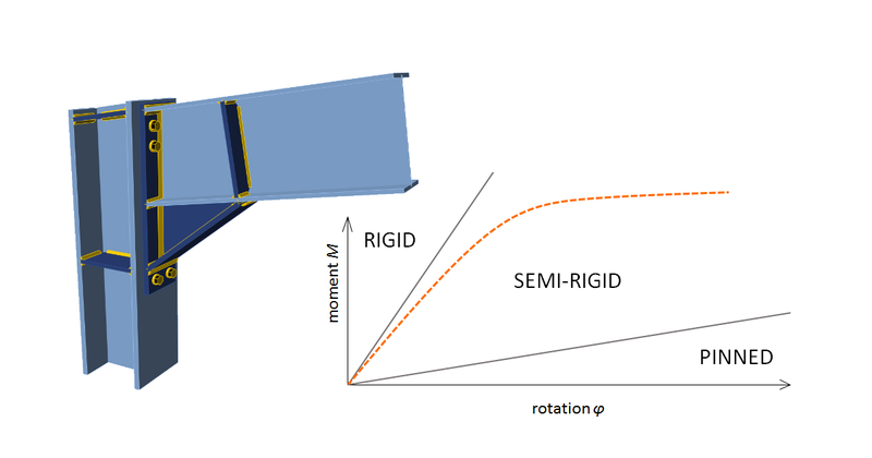
In general, the Structural engineer has to choose from 3 basic types of connections classified according to joint stiffness:
Pinned – joints that do not develop bending moments.
Rigid – joints with an insignificant change of original angles between members
and an infinite number of values in between
In the global structural analysis model, the first two options are mostly used. Contradictory, most of the real steel structure connections belong to the third group.
This classification is supported by Eurocode as well as in AISC standards. Although the nomenclature is different, the meaning is the same.
Eurocode:
AISC:
(EN 1993-1-8 sec. 5.2.2)
(AISC 360-16 Cl. B3.4)
– Rigid
– Pinned
– Semi-rigid
Moment Connections:
– Fully Restrained
– Partially Restrained
Simple Connections
For both codes, there is a bunch of requirements for a particular classification. If you want to know the details, you can simply follow the theoretical backgrounds either for Eurocode or for AISC standards. Before jumping right into assessments, some basic theory could be found very useful.
Two main problematic situations
Joints considered pinned in the global analysis model, behave semi-rigid in construction reality (transmit bending moments into connected member)
Joints that are considered rigid are not rigid enough
Mainly because of manufacturing and assembly reasons, the first situation occurs more often.
Some could say, that this inaccuracy is on the safe side and therefore it doesn’t cause any problem. And yeah, the bending moments in the span is in real structure reduced by connection moments at the edges.
But it is necessary to go further: It isn’t dangerous for the beam itself, but for the member to which the beam is connected!
Quick demonstration
Let’s show the importance of choosing the right connection for the right purpose. (And also the consequences of inappropriate connection for the global analysis)
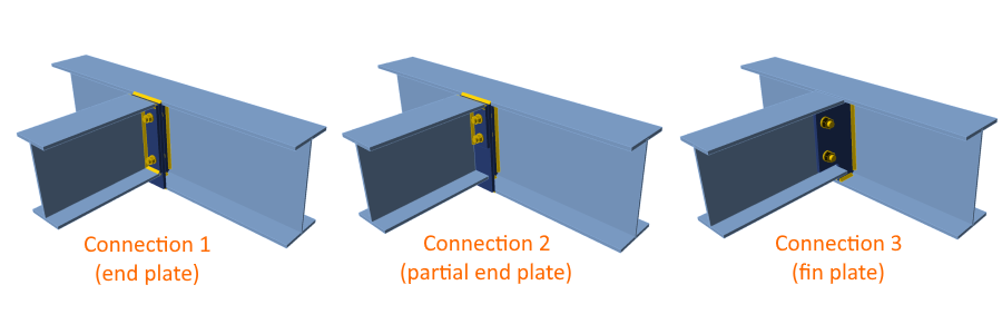
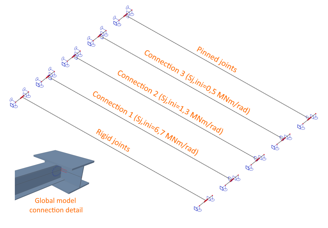
If you solve the standard connection of the ceiling girder to the main beam, you’ll have many connection alternatives. I chose three very common ones.
With IDEA StatiCa Connection you’re able to calculate connection rigidity in few seconds. For better comparison, I added extreme cases with Rigid and Pinned joints:
Rigid connection
Connection 1 (Sj,ini = 6.7 MNm/rad)
Connection 2 (Sj,ini = 1.3 MNm/rad)
Connection 3 (Sj,ini = 0.5 MNm/rad)
Pinned connection
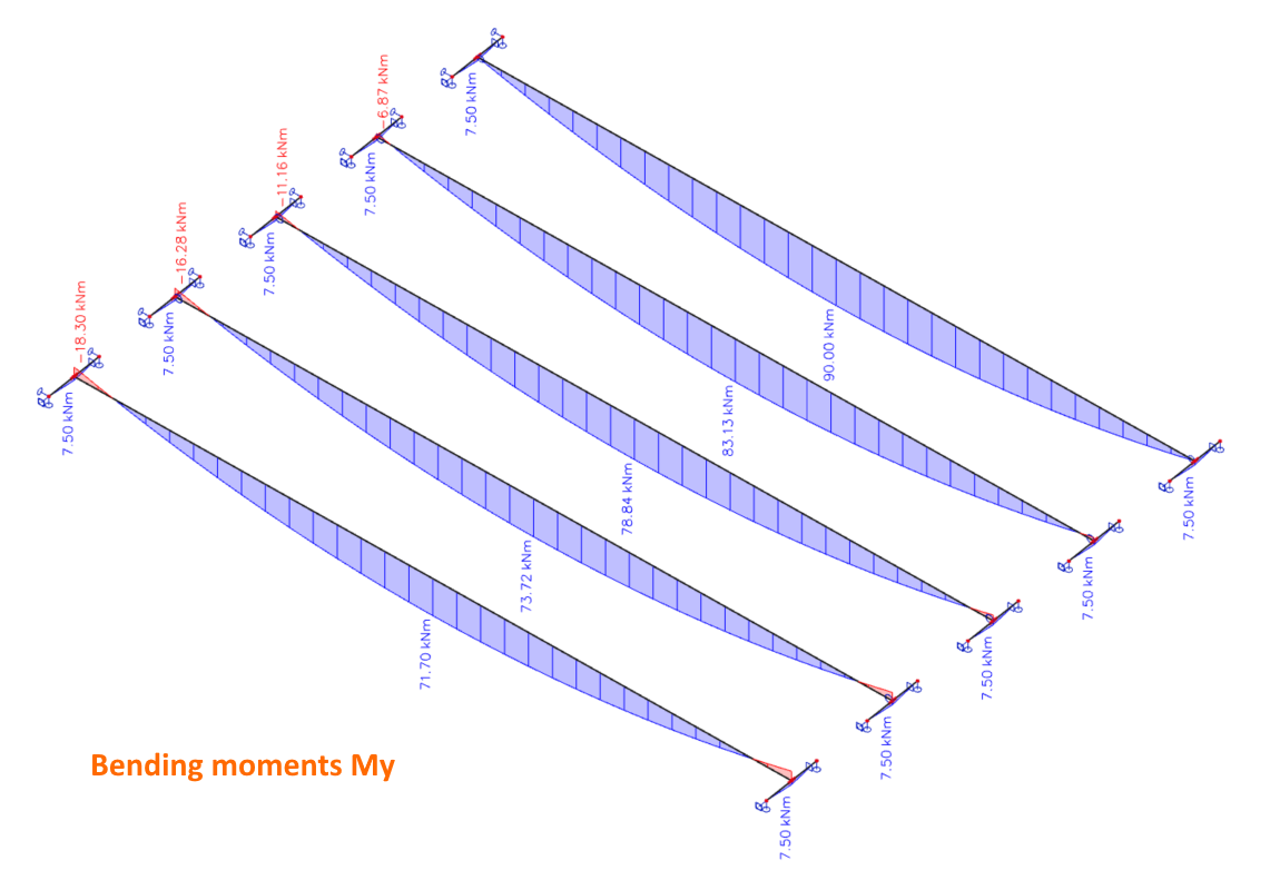
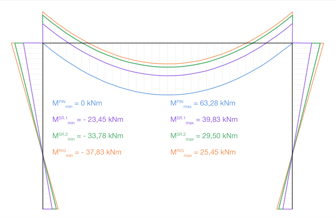
Impact of rigidity on bending moments
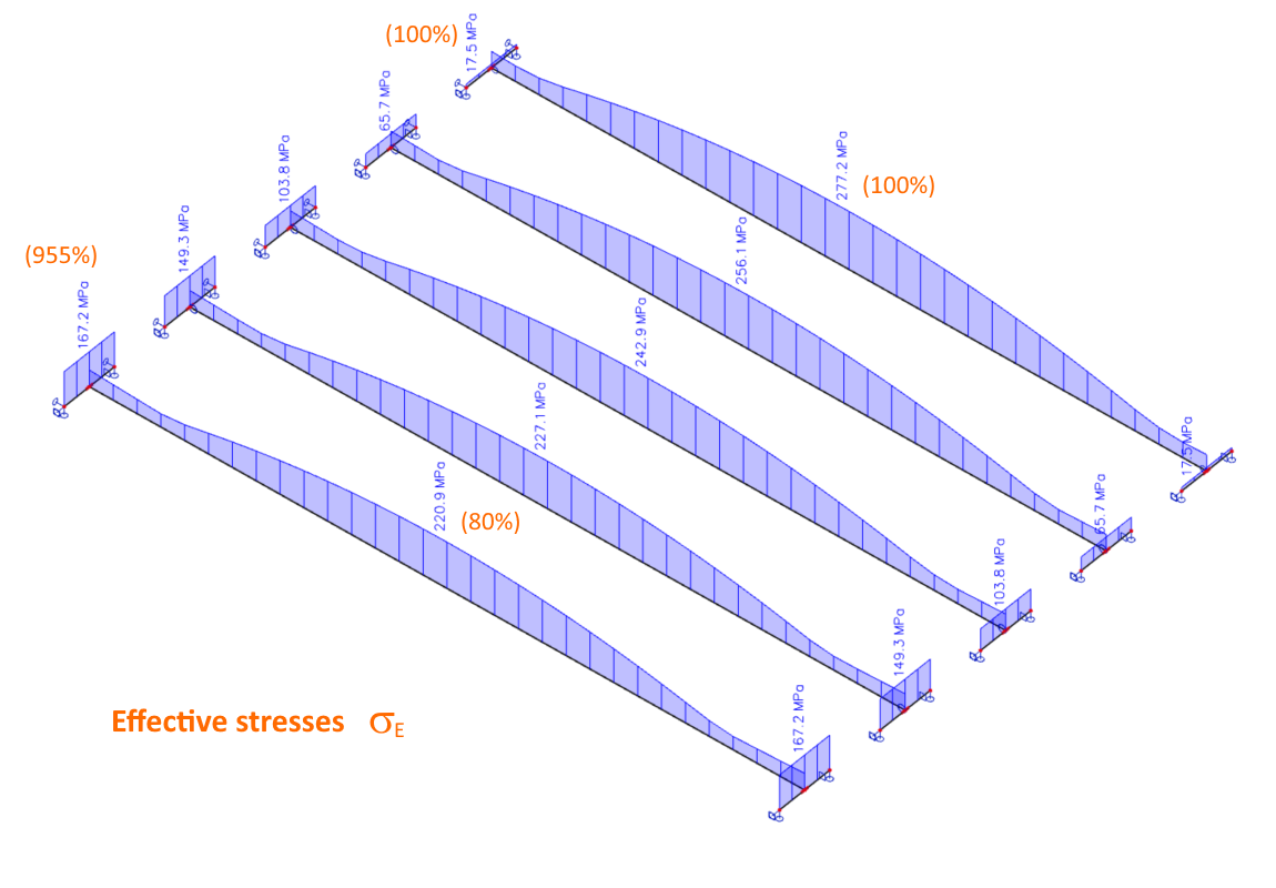
Impact of rigidity on effective (von Mises) stresses
As you can see, while the girder is used less with the connection rigidity increase, the main beam can be easily overloaded in some cases.
The common way to do it
When the structural engineer decides that real stiffness of connection should be taken into account (what should be quite often), there are several options of calculation.
manual
in a prepared spreadsheet template
calculation by dedicated software
Sample analysis
you solve simple structure with 100 linear steel members,
it means 200 ends to connect.
such structure can contain 20 types of different connection types,
you have 10 load cases and 100 generated load combinations.
It would become a nightmare to solve all connections for each decisive load combination. That’s why you calculate only the important ones. Still, it can be 10 critical connections with 2 – 6 members included and our workflow could look as follows:
1 ) Although incredibly time-consuming, connection models and calculations of their rigidity could be feasible. At least for the first run.
2 ) After Stiffness analysis is done, you can set the rotational stiffness in joints of the global analysis model. You can import it.
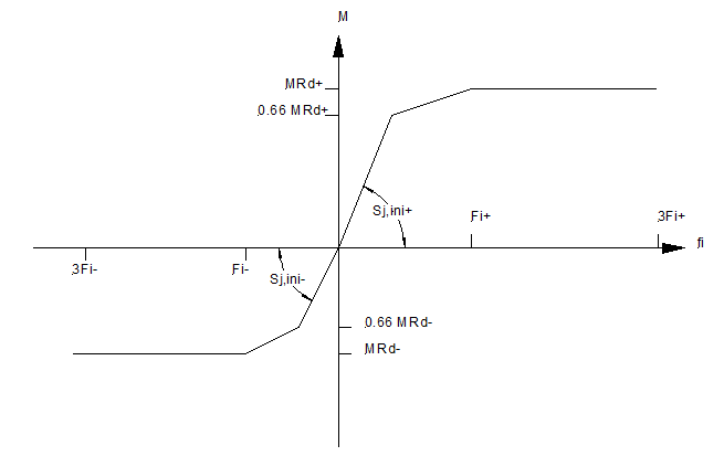
as a single value:
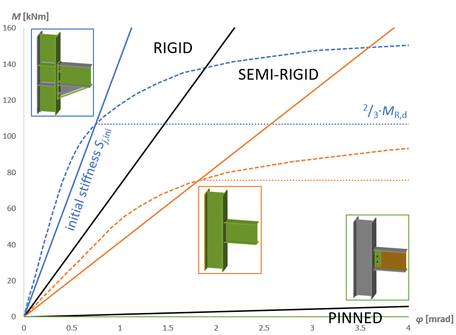
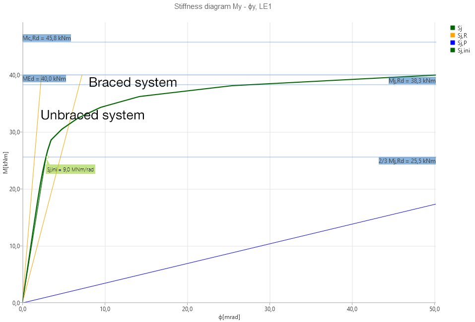
if MEd is lower than 2/3 Mj,Rd you can directly use Initial Stiffness of connection
if MEd is higher than 2/3 Mj,Rd – iteration process
or as a non-linear function:
3 ) With updated stiffness parameters you can run the global analysis, where of course new internal forces will be calculated. The influence of the new setting can be minor but also huge in some cases.
4 ) Now you need to check and revise our cross-section and the connection design. If everything suits fine, you’re lucky and can proceed to the next step of designing. More probably some changes in the original design will be needed, so you have to come back to point 1 ) and repeat the iteration process until all design components satisfy all the requirements.
The smart way to do it
The best tool for connection stiffness calculation nowadays is the IDEA StatiCa Connection application. For maximum workflow simplification and saving a lot of precious time, you can use a BIM link to export your connection design from CAD application to IDEA Connection.
Then you set the analysis type to Stiffness analysis and in a few seconds, you obtain our rigidity parameters. To be as effective as possible, some useful tips for stiffness analysis could be found in our Support center.
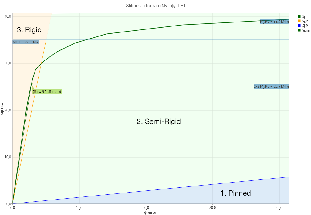
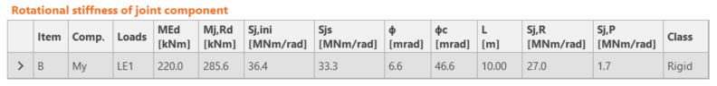
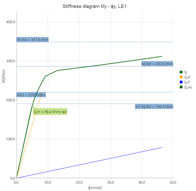
Each rigidity analysis provides immediately these precious outputs:
All the important values in one table
Graphic visualization of calculated values
Do you want to calculate the connection stiffness on your own with IDEA StatiCa Connection? Just follow the prepared tutorial for EN or for AISC standard.
The verification process of the new application had finished and the studies were published together with university teams. You can go through several verification examples.
Important facts
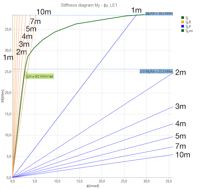
It’s worth remembering, that thesame connection can be categorized differently depending on the length of the member
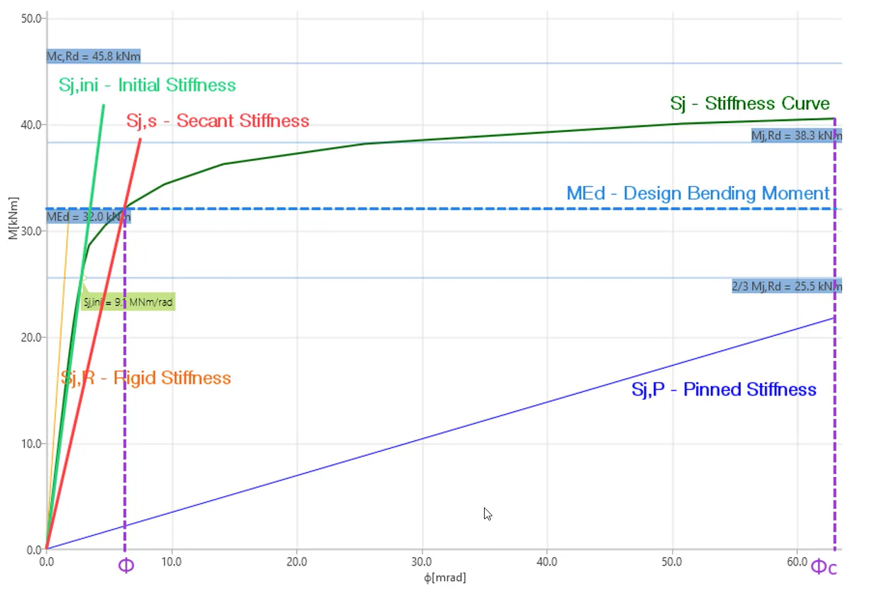
Initial stiffness (Sj,ini) isn’t influenced by Design bending moment (MEd), while it has an impact only on Secant stiffness (Sj,s)
Changes of joints’ stiffness parameters always affect the internal forces calculated in the global analysis model
In the Eurocode approach, you have to distinguish between Braced and Unbraced structural systems as the same connection could be classified as Rigid or Semi-rigid depending on bracing