Welds and bolts are the most difficult elements in the design of steel connections. Excel spreadsheets very often simplify their calculation. Modeling them in general FEM programs is complicated because these programs do not offer the predefined sets of elements. That is why the CBFEM method was developed and implemented into IDEA StatiCa.
Weld model according to CBFEM
IDEA StatiCa has a unique method in its solver, the Component-based Finite Element Method (CBFEM). The weld model used in CBFEM is described and verified to several steel design codes. The load resistance and deformation capacity are also compared to the main experimental research programs.
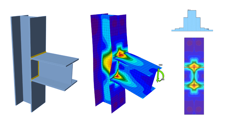
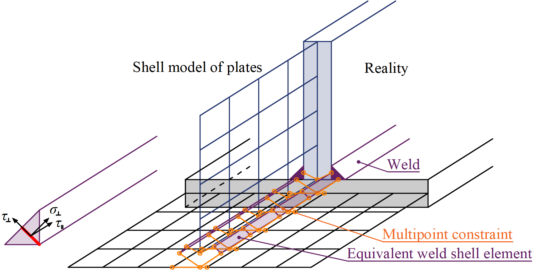
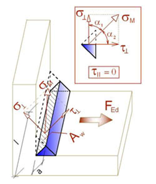
There are several options on how to treat welds in numerical models. The large deformations make the mechanical analysis more complex and it is possible to use different mesh descriptions, different kinetic and kinematic variables, and constitutive models. Generally, different types of geometric 2D and 3D models and thereby finite elements with their applicability for different accuracy levels are used. The most often applied material model is the common rate-independent plasticity model based on von Mises yield criterion. Residual stress and deformation caused by welding are not assumed in the design model.
The load is transmitted through force-deformation constraints based on the Lagrangian formulation to the opposite plate. The connection is called multi-point constraint (MPC) and relates the finite element nodes of one plate edge to another edge or surface. The finite element nodes are not connected directly. The advantage of this approach is the ability to connect meshes with different densities. The constraint allows to model midline surface of the connected plates with the offset, which respects the real weld configuration and throat thickness. The load distribution in the weld is derived from the MPC, so the stresses are calculated in the throat section. This is important for the stress distribution in the plate under the weld and for modeling of T-stubs.
In our Theoretical background, you can find more information on how the CBFEM method describes and verifies welds.
If you want to know a bit more about CBFEM in general, the full General theoretical background is definitely the best place to start from.
Welds according to codes and standards
Welds according to AISC
Fillet welds are checked according to AISC 360 – Chapter J2. The strength of CJP groove welds is assumed the same as the base metal and is not checked. As most of the IDEA Statica users are already used to, all values required for checks are printed in tables.
When it comes to weld detailing, the minimal and maximal weld size and the sufficient length of the weld are checked. The maximal weld size is checked according to AISC 360-16 – J2. The minimal weld size is checked according to Table J2.4. A detailed description of the parameters can be found in this article.
To give you peace of mind that your designs are complete and accurate, IDEA StatiCa results are being thoroughly tested and verified according to AISC requirements:
Welds according to Eurocode
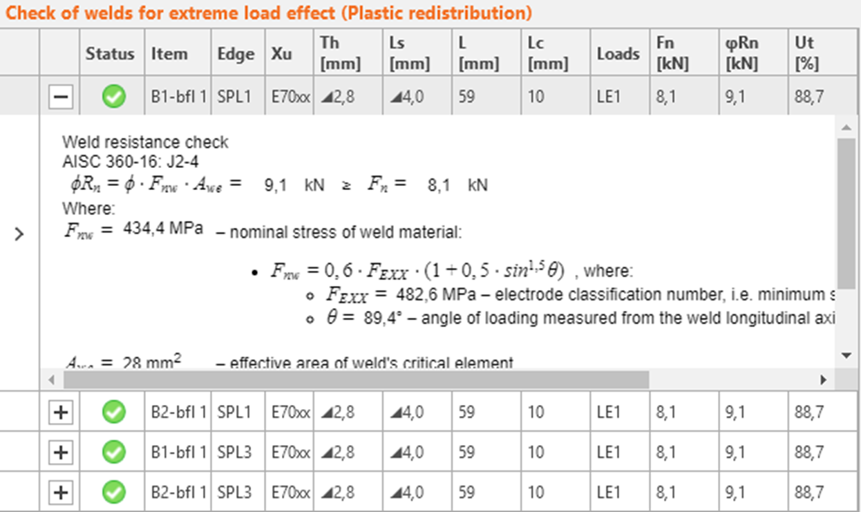
Fillet welds are checked according to EN 1993-1-8. In this case, the engineer’s concern is the design resistance and weld utilization.
The plastic redistribution in welds is used to automatically avoid the stress singularities in weld elements, to redistribute the stress further along the weld length.
It is also important to be aware of the premise, the strength of butt welds is assumed the same as the base metal and is not checked.
To read more about the weld check according to Eurocode, our Theoretical background can be of help again.
Verifications of welded connections according to Eurocode:
Welds according to other codes
Most of you already know, IDEA Statica enables you to check steel connections according to eight national codes and standards so far. Except for the above-mentioned AISC and Eurocode, here is, how welds are treated by CBFEM in the remaining codes:
- Weld check according to CISC (Canada)
- Weld check according to AS (Australia) + Weld detailing
- Weld check according to SP (Russia) + Weld detailing
- Weld check according to GB (China) + Weld detailing
- Weld check according to HKG (Hong Kong) + Weld detailing
- Weld check according to IS (India) + Weld detailing
Weld transmission in BIM links
When modeling a steel connection in CAD software with IDEA StatiCa BIM links, there used to be a few weak spots when it came to welds. The new IDEA StatiCa version 20.1, released in October 2020, brought several improvements to ease the engineer’s life and speed up the design process.
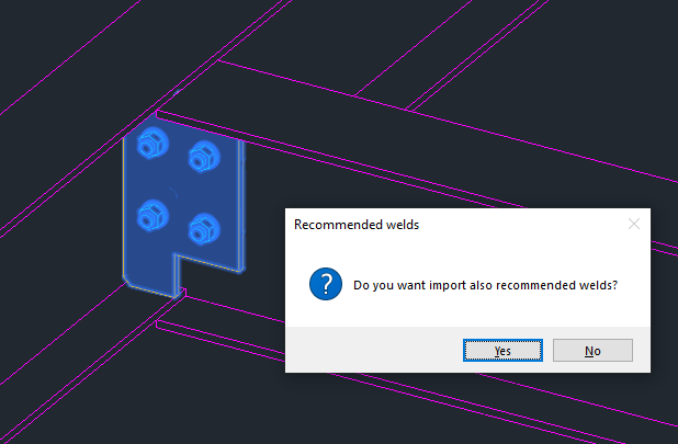
Export of recommended welds
Sometimes, during the modeling process in CAD software, a few welds might be omitted or not imported correctly. For such situations, there is now an option to add recommended welds. When you choose this option, a check for potentially missing welds is performed. Such welds are then added and imported along with the rest of the components.
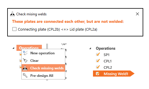
Missing weld check
To avoid singularity on your connection, once the connection is transferred to IDEA StatiCa, it is good to check if there are not any missing welds in the joint. For this purpose, we have added another useful tool to automatically help the user to find non-welded parts of the connection. This feature identifies and lists all the relevant plates and plate edges and allows the missing welds to be added.
You can enter this functionality by the right-mouse click on Operations in the tree of entities on the right side of the scene.
Summary
Connection design in IDEA StatiCa contains a verified CBFEM model of welds that allows code checks, realistic stress redistribution, and connecting plates with meshes of different densities. The validity of results is shown on a set of examples for each design code. The finite element model is being generated automatically, which is a great advantage to general FEM programs. Recently, several improvements were added to speed up the connection import process from CAD software.
Welds are a great way to assemble steel connections but engineers need an accurate and fast tool for their design and code-check. That is why to use IDEA StatiCa in your projects.
If you want to improve your connection design skills, why not try our IDEA StatiCa Campus online training?