Exploring Key Principles of Idea Statica Connection
IDEA StatiCa Connection changed the game in steel connection design a couple of years ago with a clear message – a software tool that is simple to use, and powered by the most sophisticated methods. With that being said, there are several principles an engineer should always keep in mind.
The appreciated user-friendly UI of IDEA StatiCa Connection allows structural engineers to work efficiently on everyday tasks as well as on complex projects. Quick and well-arranged input and overall automatization of the CBFEM analysis with a clear result overview don’t leave any room for dead ends or process errors.
However, one should not be comforted, this is still a tool dedicated to engineers who need to consider a couple of facts and rules of the structural design. So, what is it you shouldn’t forget when starting a new connection project?
You can find the condensed answer on this webpage Key principles of IDEA StatiCa Connection. Pointing out the essentials, every user of IDEA Statica Connection is more than recommended to read this. Let’s highlight some.
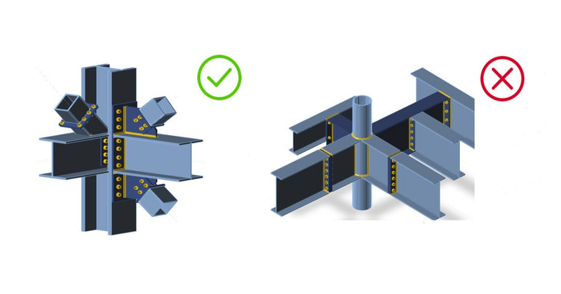
A connection model consists of one structural node
A common question our users ask is, how complex my connection model can be? Though we claim no limits in topology or loading, there are some limits considering the engineering judgment. In other words, the structural model consisting of a node and connected beams and columns in your structural software (SAP2000, SCIA Engineer) must correspond to the real connection model used in IDEA StatiCa Connection.

The load effects that you input are the nodal internal forces
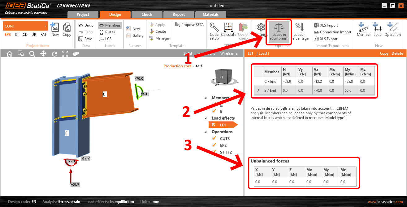
Another frequent misunderstanding is in inputting the loads for the analysis of your connection. So those are the internal forces you get as the results from your structural model and after that, you use it for the connection analysis and code-check. By the law of statics, internal forces in a node have to be in equilibrium, meaning if you sum up them in each direction, you get zero. For most cases, have the Loads in equilibrium turned on and input the internal forces for each member. Then you can visually check that the unbalanced forces tab shows all zeros.
Position of shear force can be moved
By default in the connection model, the internal forces are positioned in the node as they are in the structural model. However, the program allows for more position options. That is necessary for analyzing e.g. pinned shear connections when there should be zero bending moment in bolts or zero bending moment in the weld necessary for proper code-check.

To keep you on the right track, we provide you with more materials to read and watch. Out of many videos and webinar recordings, we picked the most appropriate for this topic here for you:
The most common mistakes made in connection design and how to avoid them
What is the correct position of forces? Which model type is the right one? Why do I get bolt errors if the 3D scene looks well? Why can’t I cut or use the splice operation on my stub? Most common but still not easy-to-understand questions the users of IDEA StatiCa Connection could come to, all demonstrated in this presentation.
3 most common traps in connection design
We know that every one of you has sometimes a headache with connection design project requirements. How is this connection going to behave? Why did the calculation fail? In this webinar, learn about bolts and composed steel cross-sections and their potential errors or deepen your skills with stubs and their behavior in splice operations. Last but not least, explore more on mesh topology errors and why importing plates from DXF is not always the best way.
Based on real examples we have received through our support channel, power up your modeling skills the best way – learning from mistakes done by others. This webinar touches on features like the wireframe model, how to avoid defining eccentricities at the member level, cutting with work plans, the use of stiffening members, and general anchoring to the rescue.
What else? See even more video content on our IDEA StatiCa YouTube channel or dive into our short knowledge-based articles found on the Online Support Center. If you have any questions, our helpdesk can be contacted via the User portal.
Author of this news article:

Adam Kozousek
Product Engineer IDEA StatiCa