We develop software for structural engineers and detailers. Our development team researches, tests, and applies new methods of analyzing the behaviour of structures and their members. Based on this, we created IDEA StatiCa – software that enables engineers to work faster, evaluate requirements of the national code thoroughly, and use the optimal amount of material. For us, creating software is a way to contribute to making every new construction around the world safer and cheaper.
Design of eccentrically connected bracing members
We could find them in almost every structure. Structural members come into the node with eccentricity from the ideal axial position. Is it still safe to neglect the eccentricity, or should it be considered? Frequent questions with no general answer.
Every steel structure detailer knows this situation. Overall structural analysis model has all the member axises coming nicely directly into the structural node. And the structural system is nice and clean. But the real structure is a different story.
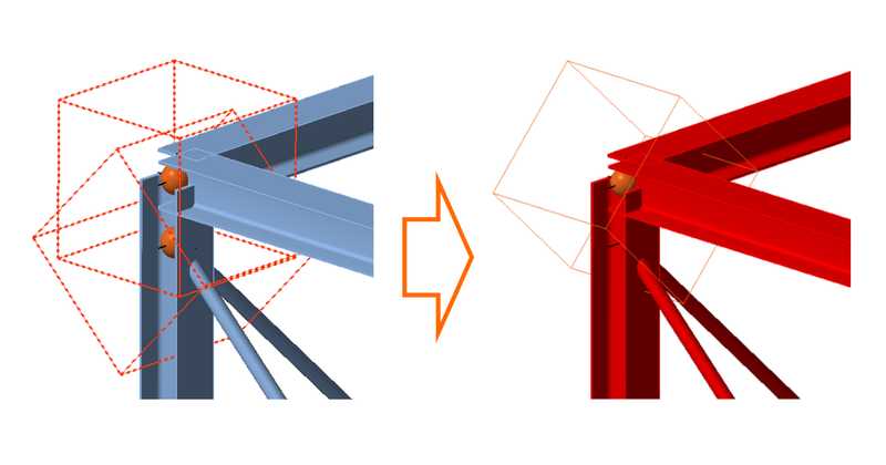
An example case is a beam-to-column connection with the bracing members somewhere near. In this connection, the column is the only member with an axis position identical to the structural model. The beams hve their top flanges aligned, so in case the beam depths differ, the axes are at different levels.
And what’s an even more common difference, the axes of bracing members have eccentricities to the optimal in-nodal direction. The reasons for this vary – it’s due to the fabrication, constructability, or aesthetical purposes. Quite often, the ideal direction of bracing members would cause unreasonable big gusset plates or collisions with other members. Sometimes other technology or equipment could be the reason for shifting the bracing members from the node.
And then the #1 standard question arises:
Will this shift have some impact on the bearing structure?
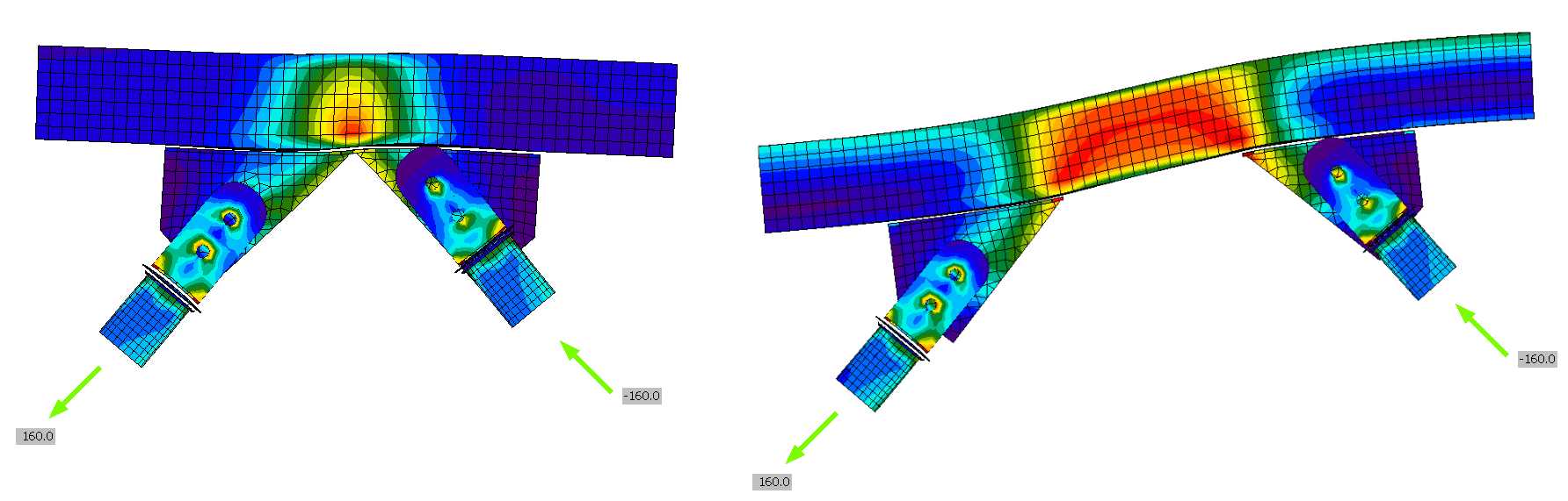
The answer is easy – yes, it will. Additional secondary internal forces are induced into the structural members. These are the shear forces, bending, and torsional moments. Sometimes reducing and other times increasing the stresses on members.
Usually followed by standard question #2:
Is this influence worth introducing these eccentricities into the original overall structural model?
That’s the tough one!
I would guess that in the majority of cases, these eccentricities in details are neglected in the model of the whole. And it’s understandable. The situation would have to be quite non-standard to cause any significant trouble. But it can happen but it is not obvious, and if it is not obvious, it’s potentially dangerous. And structural engineers like the safe side.
One example of a safe scenario:
The structural engineer calculates the main bearing structure and moves the working FEA model to the Detailer.
The Detailer brings the model (with the BIM export/import or manually) to the CAD application, where he designs all the connections necessary for fabrication and erection.
Then he needs confirmation from the Engineer that the proposed connections are in compliance with the specific design code requirements. So, he moves the CAD model back to the Engineer.
The Engineer finds the differences between the original geometry and the construction geometry from the Detailer. And now the crossroad appears.
a) He or she makes a quick review of the design and assesses it based on his or her experience.
b) He or she applies the original forces to the Detailer’s new geometry and analyzes the connections.
c) He or she changes the original FEA model according to the CAD model, calculates everything again, and analyzes the connections.
Where is IDEA StatiCa used in this scenario:
4 b) and 4 c) are exactly where the Checkbot and IDEA StatiCa Connection apps have their biggest strengths. And that’s because of the Checkbot’s ability to recognize and process the structural models from various software of both environments – FEA and CAD solutions.
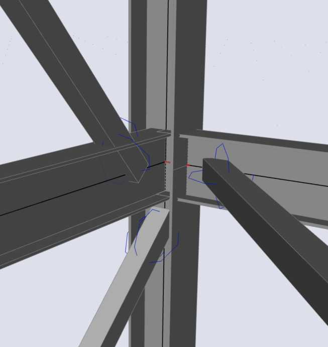
(example of FEA model with eccentricities)
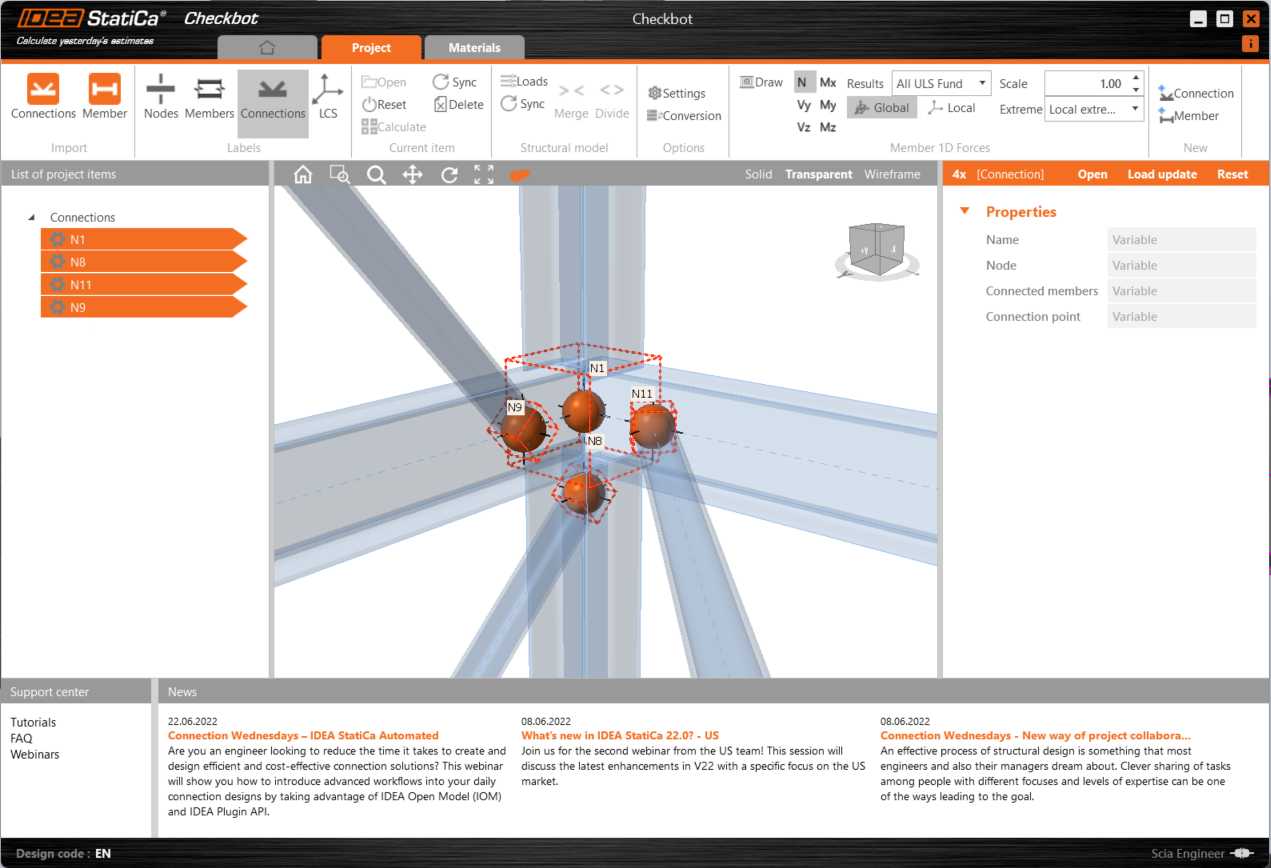
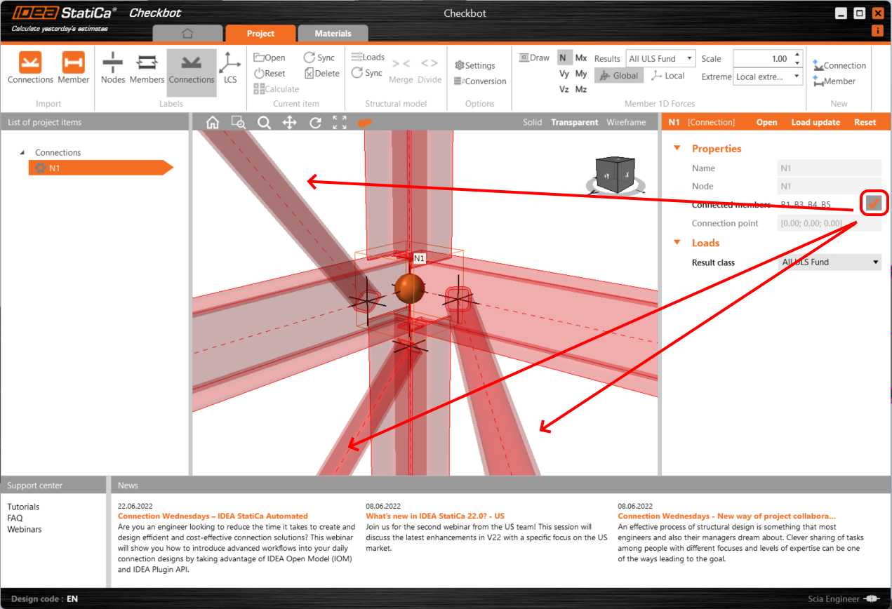
Once the model is in, it’s very easy to select a specific structural node and assess it in the Connection app.
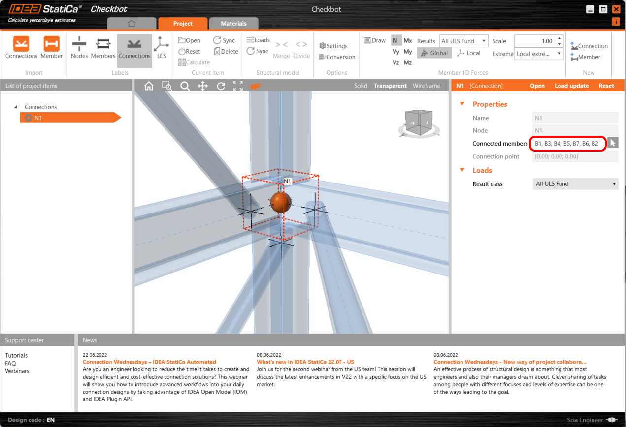
The situations with the members coming into one connection but not in the exact same node couldn’t be solved easily until version 22 was introduced. These were evaluated as separate Connections, and the user had to help himself by manual editing. From the IDEA StatiCa Connection v22 on, the grass is much greener for the user. The Checkbot either automatically recognizes that the very near nodes belong to the same connection, or the user can manually select which members should be involved.
This way, we can set a specific set of members involved in the particular Connection model.
This was maybe a small improvement in the user interface but a quite important step towards the goal of analyses of the real structures and not only the theoretical ones.
So, regardless of Engineer’s choice between paths 4 b) or 4 c), in both cases, the connection analysis can be quick, and the fear of an unsafe solution can be eliminated. And that’s what we like.
If you’re also interested in other improvements provided in IDEA StatiCa 22, you can go through our Release article here.
Did you like this post? Don't miss similar topics!
Join 10,000 fellow engineers and get expert engineering tips straight to your inbox.