Lateral Torsional Buckling
When you first heard the term lateral Torsional Buckling (LTB) at university you were a student who had no real idea of the importance of this phenomenon. That being said, you quickly understood just how important this topic is!
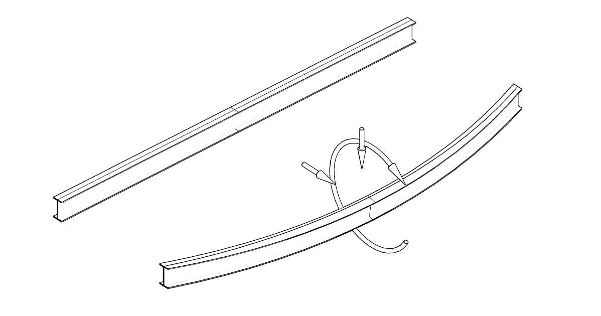
Lateral torsional buckling (LTB) is the deformation of an unrestrained beam due to the applied loads away from its longitudinal axis – both lateral displacement and twisting.
Unrestrained steel beams are beams whose compression flange is free to move (or displace) in the lateral direction and also rotate. If we apply this theory to a simply supported beam then the compression flange is the top flange. As this flange deflects laterally the tension flange tries to keep the beam straight and creates ‘restoring’ forces due to the lateral bending of the beam. However, these forces alone cannot keep the beam straight. The resistance of the beam to LTB is determined by the restoring forces and the lateral component of tensile forces in the tension flange.
The interaction of the compression and tension flanges forces an unrestrained beam to twist. The resistance to this twist is dependent on the torsional resistance of the beam section. Beams with large flange thicknesses, for example, have a greater torsional resistance than those of lesser flange thicknesses for any given depth. There are other sections that also offer greater resistance (RHS/SHS) and these are often used in situations where there is a need for large(ish) spans to carry the vertical load (e.g. openings involving bi-fold doors) which are prone to out of plane force effects.
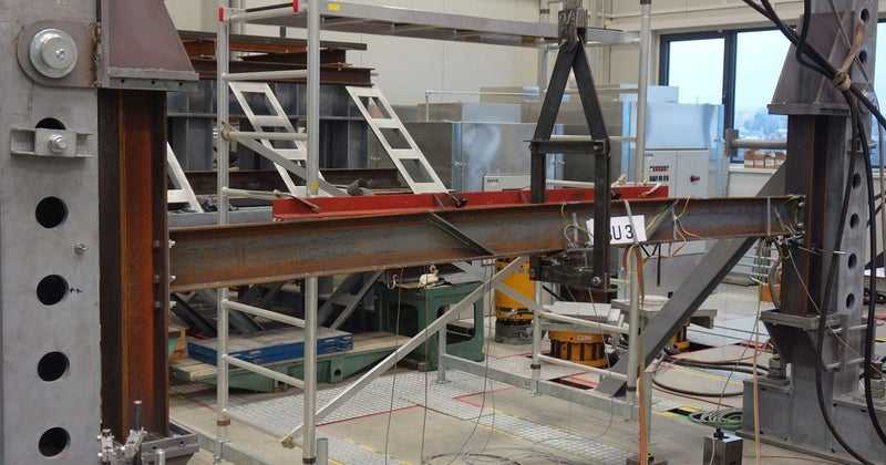
To see how the LTB failure propagates take a look at this video.
What factors influence Lateral Torsional Buckling?
There are three main factors:
- Location of the applied load
- The bending moment distribution
- End support conditions
1. Location of the applied loads
The effect of LTB is governed by the distance between the location of the applied and the shear center of the beam section. The section is more prone to LTB is the load is applied above the shear center. The effect is less if the load is applied along the shear center and if applied below then the beam has little chance to undergo LTB.
[Aside] The shear center is a point on the beam section where the applied loads do not cause its twisting. It is dependent on the cross-section. The shear center and center of gravity on a symmetrical section are the same. They may not coincide on an unsymmetrical section. There is a bit of mathematics involved in computing the shear center for any given section but luckily engineers use software and have tables that they can refer to!
2. The bending moment distribution
A section with a uniform bending moment along its length has less buckling resistance compared to a different bending moment distribution.
3. End support conditions
The LTB resistance of a beam section increases as the end supports become more restrained. Consider a beam resting on a padstone compared to the beam cast into a concrete wall. The latter has more restraint at the ends than the former. One is free to rotate and one cannot.
Design considerations with IDEA StatiCa
Providing effective lateral restraint can benefit the size of the beam considerably. Restraint can be fully achieved by the composite action of a concrete deck. Partial restraint can be achieved using intermediate beams. Bracing – of sufficient size and suitably located – can also be used.
This is all well and good for member design but what happens when it comes to connection design?
The actual reactions remain the same irrespective of the LTB restraint, but the member has additional fixity because of this restraint. If we ignored this, then the connection design would be an overestimate.
In the new version of IDEA StatiCa (version 22.0) we have introduced a new operation – Lateral Torsional Restraint – to enable our users to take this into account if they so wish.
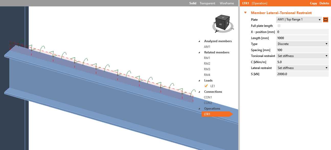
Find more information about the Lateral Torsional Buckling Restraint feature. This operation avoids torsion of the member in the connection and allows more economical design while maintaining the required safety.