
IDEA StatiCa Connection is an easy-to-use tool. It takes approx. 30 minutes to estimate its potential and a couple of hours to learn the basics. But what if you get an error message? Do you know, how to repair your model? Let us guide you through the seven most typical mistakes or error messages you can come across with when using IDEA StatiCa.
#1 Singularity warning on a simple joint
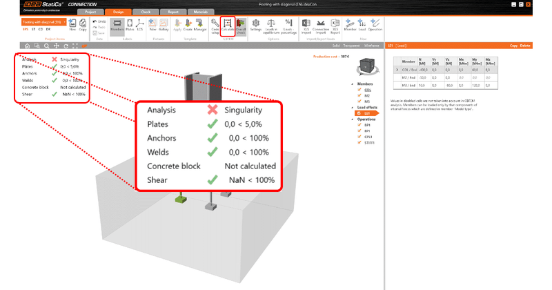
Case: I designed a simple joint. After the calculation, I got a singularity warning.
What does it mean?
Singularity warning is without any doubt the most reported and noted question on our Support Center. It is an analysis stop warning of occurred mathematical nonconformity. This issue is mostly caused by elements not correctly connected to the members.
In fact, this warning saves your time because, in case of incorrect model setup, the analysis might take a lot of time without giving you any reliable result.
Once you understand the warning, it is quite easy to discover the issue and repair it. In the article “What is the Singularity warning“, you can find a couple of good hints and advice on how to get rid of that.
By the way, just recently we added a new feature Check for missing welds which might help you a lot before you even run the first analysis.
#2 Singularity warning on one bolt connection
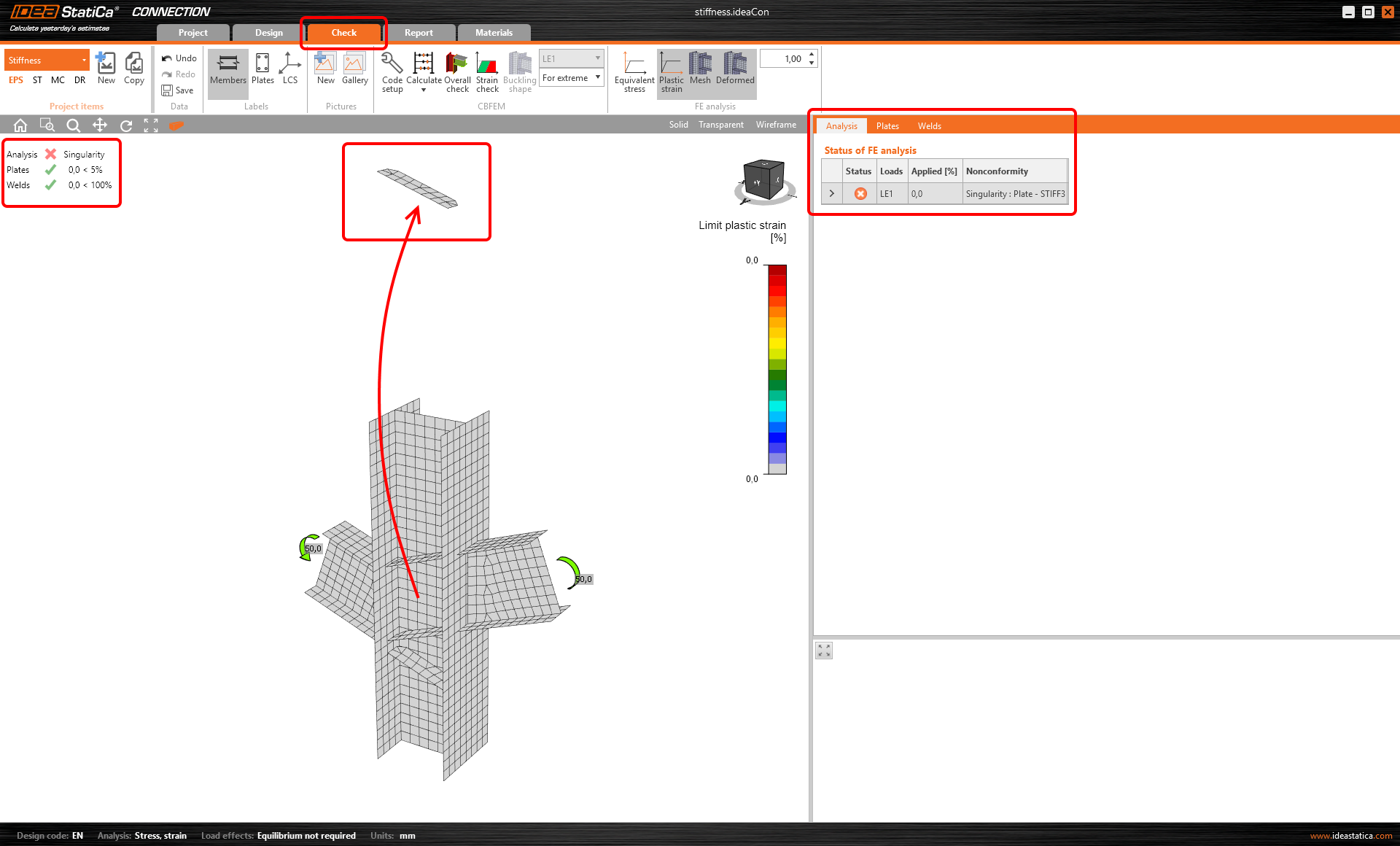
Case: I have a connection with one bolt, but the software gives a singularity warning.
What is the reason?
Sometimes, the engineer needs to make a joint with one bolt only, especially if the hinge is expected. Connecting two items together with one bolt is absolutely possible with IDEA StatiCa, of course. But applying a moment to the joint changes it from a regular connection into a mechanism. For that reason, we implemented a feature called “Model type” to allow only selected types of force.
If you want to know a bit more on this type of issue, the best way is to go through our article:
“How to model one bolt connection”
#3 Singularity warning on circular hollow sections
Case: I need to connect a tube to a plate with a weld, but I get a singularity warning.
What shall I do now?
Another situation when you can obtain a singularity warning is caused by the non-fitting division of the circular surface to discrete angular surfaces. This happens very often when welding the tube along its length.
Resolving this error is pretty easy, needs just a small adjustment of the Code setup. Just change the default value 64 of the Division of surface of the biggest circular hollow member.
A more detailed description of this issue including its solution is described in this article: Singularity on hollow sections
#4 Bolts are too close to the plate edge
Case: I designed a simple plate-to-plate connection but got a warning “Bolts are too close to plate edge”. What is the best way to solve this conflict?
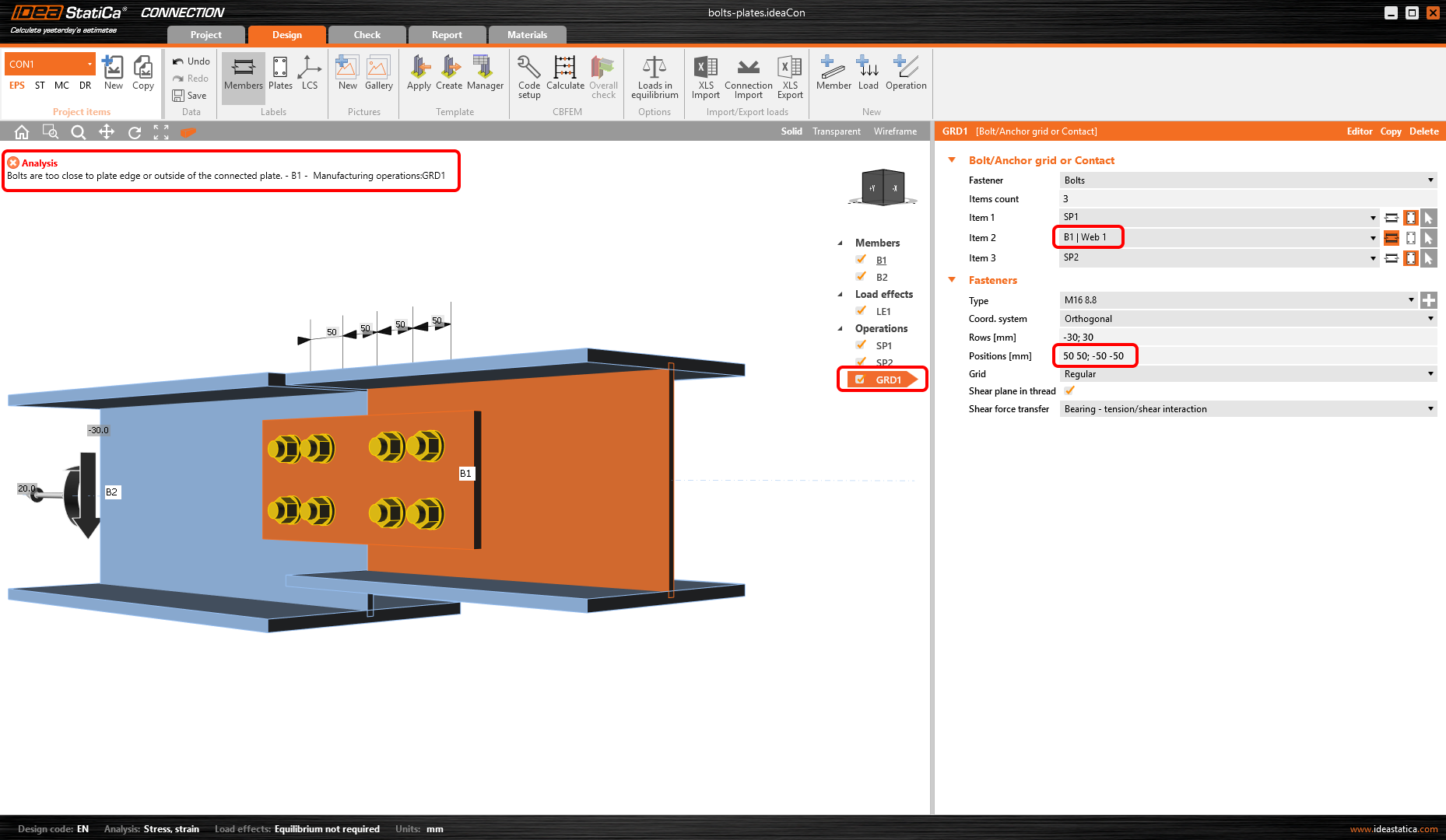
Receiving this error message can have two reasons, basically. Either that the mesh could not be generated around the bolt’s hole as there is not enough space for it. Or that the bolts are not associated with the correct plate.
Both cases are described in our Support Center article “Bolts are too close to plate edge“
#5 Singularity warning on the connection between plates
Case: I have a bolted connection between two plates. When computing the joint, I get a singularity error. What’s wrong?
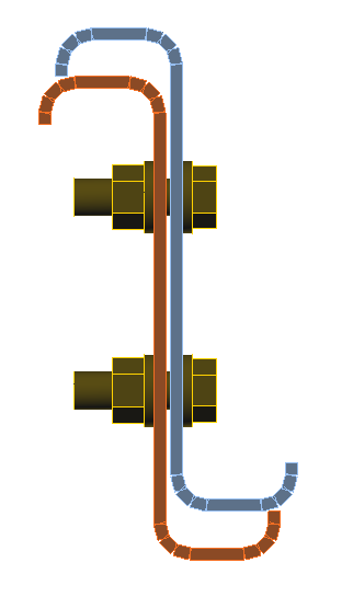
While modeling a contact or connection between plates, you have to keep the minimum distance. The operation Bolt grig or Contact is able to connect more items together, even if they are not exactly lying one of another. The minimum distance is 2 mm and if the gap between plates is bigger than 2 mm the analysis can’t be performed.
Details about this design error can be found in this article: Distance between plates when using Bolt or Contact
#6 Anchors were not calculated
Case: I have an anchoring joint with several anchors, but when performing the analysis, I get a message Anchors not calculated. Why?
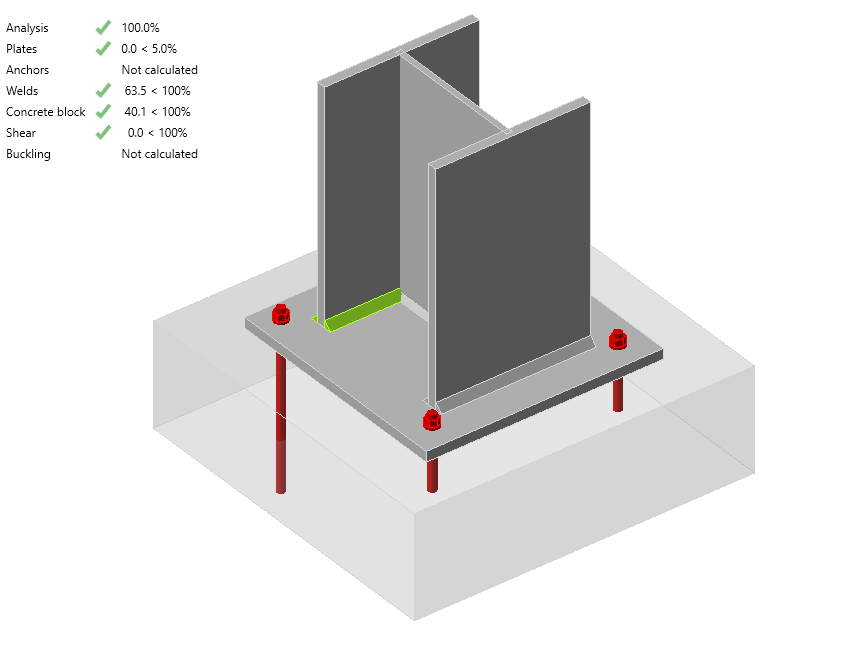
According to EN 1992-4 – Cl.1.2 (4), the anchors must be of the same type. If not, the code checks cannot be applied to this anchorage. So the anchors need to be of the same type, diameter, and embedment.
#7 Local deformation limit
Case: I analyzed a hollow section joint. The analysis was OK, but welds and/or plates are exceeding 5% / 100%. What happened?
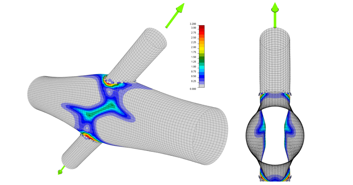
In case you have a hollow cross-section, a local deformation check is implemented. But this check is not included in the overall check. So, you have to go to the Tab Check and see detailed information on plates and welds on the right side. There is a 3% limit set according to the CIDECT code.
You can find some more info about this topic in this article: Local deformation check for the hollow members; more explanation in our Theoretical background- Joints of hollow section cross-section members.
Summary
We have gone through seven issues our users are asking for help with most often. As you can see, all these mistakes are clearly visible and visualized in IDEA StatiCa and easy to be corrected. Don’t be afraid to put IDEA StatiCa to the test and in case, you come across an error or failure you are not able to solve, there is always a way to help you. Either search through our rich Support Center or ask our support team via the chatbot.